194002120 - INTRODUCTION - SUSPENSION AND WHEELS
INTRODUCTION
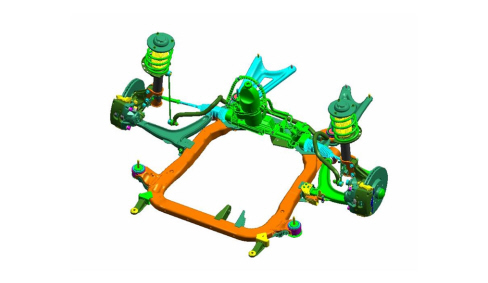
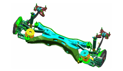
The suspension provides the physical connection between the vehicle and the road producing a direct effect on the driver by the forces generated by the vehicle''s progress. This effect is transformed into sensations that are felt by the driver''s body and/or through the steering.The forces generated by the progress of the vehicle are transferred to the driver by the wheels by means of the suspension components with mechanisms that dismantle the actual forces that are very important for the performance of the vehicle.The front suspension is the Mc Pherson type.The rear suspension is the independent multilink type.PERFORMANCE
The design of the suspension and the calibration of the various elements together with the tyres contribute in determining two important aspects of the behaviour of the vehicle:- driveability (handling);- driving comfort (ride).In short it can be stated that the level of performance of a vehicle in terms of handling and ride depends on how and to what extent the suspension carries out the check on two fundamental parameters:- the position of the wheel in relation to the ground;- the vertical and lengthwise movements of the wheel.FRONT SUSPENSION
Specifications
Different aluminimum components are used for the front suspension to reduce the effect of the suspended masses. This light structure makes it possible to reduce fuel consumption. The suspension is made from the double strength frame to offer better handling and improve behaviour in the case of an accident.The use of hydraulic bearings makes it possible to dampen noise and vibration improving driving comfort.The modular structure of the suspension considerably reduces fitting times.Components
Chassis
The chassis is made using the innovative "pipe hydromoulding" technology that makes it possible to produce an optimum shape and thickness reducing the use of welds. The fitting of the chassis on the underbody also involves the use of four damping bushes.Coil springs
Greatly offset in relation to the shock absorber to reduce ungluing friction. The springs, which rest on upper and lower shims with rubber seals in between to prevent noise during operation, are highly flexible to produce excellent driving comfort in all load conditions.End of travel buffer
Made from "cellasto" with very gradual intervention for an improved and smooth response round bends and in impacts.Anti-roll bar
Connected by means of a connecting rod to the shock absorber for improved responsiveness when cornering.Shock absorbers
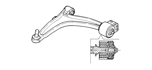
Double acting, pressurized, hydraulic shock absorbers to reduce operating noise. A teflon band built into the piston replaces the oil scraper ring and reduces sliding friction.Lower track control arm
In forged aluminium with a ball joint incorporated for connection to the damper. The two connections to the suspension frame are achieved through bushes, the rear one is the hydraulic type with metal plating. The hydraulic bushes cannot be reconditioned, in other words, if there is no anti-freeze (glycol) it cannot be repaired and therefore needs replacing.Yield type tightening torques
The yield point type tightening torques for the front suspension are listed below. These fastenings (nuts and bolts) must be replaced at each refitting.
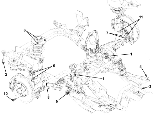
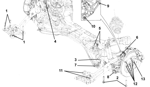
1. Nut securing power assisted steering box to front suspension frame2. Front/rear bolt securing front suspension frame to bodyshell3. Inner bolt securing frame mounting bracket to bodyshell4. Outer bolt securing frame mounting bracket to bodyshell5. Bolts securing front shock absorber to steering knuckle6. Bolts securing front shock absorber mounting to bodyshell7. Bolt securing lower track control arm to steering knuckle8. Front bolt securing lower track control arm to frame9. Rear bolt securing lower track control arm to frame10. Bolt securing wheels11. Bolt securing front wheel hub to steering knuckleREAR SUSPENSION
Specifications
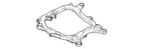
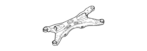
It is the multilink type with three transverse arms and one longitudinal arm. The construction diagram shows how the suspension closes completely on the crossmember which acts as a connection to the bodyshell less than the connection to the longitudinal arm.Components
Crossmember
Made from pressed steel in order to guarantee structural strength without penalizing the requirements of lightness. The crossmember is connected to the bodyshell by four bolts and supports the lower arm, the camber control rod, the toe in control rod and the anti-roll bar.Rear track control arm
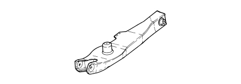
In aluminium alloy it is connected to the crossmember by means of flexible bushes. The technology used for producing the track control arm has made it possible to achieve a box shape thereby improving the strength/weight ratio without altering the properties of resistance to the stresses to which it is subject. The track control arm guides the movements of the damper and acts as a support to the spring and can be adjusted through the correct setting of the camber.Damper
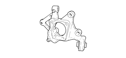
Made from cast iron, ideal for guaranteeing the correct compromise between robustness and the particular shape due to the required geometric restrictions. It is a load bearing element for the wheel wheel through which the forces exchanged between the ground and the suspension pass.Upper track control arm
Made from a steel box section it has made it possible to achieve high rigidity values in spite of the arch shape to the particular housing. The rod is connected to the damper by flexible bushes and guides the movement maintaining the correct camber value in all positions.Front track control arm
it guides the toe in movement of the steering knuckle to which it is connected by means of a flexible bush and can be adjusted to the correct setting value.Flexible and damping elements
The spring and end of travel buffer act on the rear track control arm whilst the anti-roll bar shock absorber act directly on the steering knuckle.Yield type tightening torques
The yield point type tightening torques for the rear suspension are listed below. These fastenings (nuts and bolts) must be replaced at each refitting.
1. Bolt securing rear suspension longitudinal anchorage strut to bodyshell2. Bolt securing rear suspension crossmember to bodyshell3. Bolt securing rear suspension anti-roll bar to crossmember4. Bolt securing rear suspension anti-roll bar joint to stub axle5. Bolt securing rear suspension upper track control arm to crossmember6. Bolt securing rear suspension upper track control arm to stub axle7. Bolt securing rear suspension front track control arm to crossmember8. Bolt securing rear suspension front track control arm to stub axle9. Bolt securing rear suspension rear track control arm to crossmember10. Bolt securing rear suspension rear track control arm to stub axle11. Bolt securing rear suspension longitudinal anchorage strut to mounting bracket12. Nut securing rear wheel hub to steering knuckle13. Bolt securing wheelsTPMS SYSTEM
General specifications
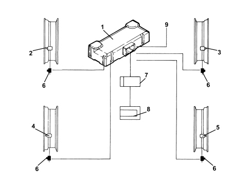
The TPMS Tyre Pressure Monitoring System checks the pressure of the tyres sending the necessary information to the Body Computer via the A-Bus network.In particular, if the inflation pressure is higher or lower than it should be, the system activates an insufficient pressure signal in the instrument panel or warns that one or more of the tyres is punctured.The tyre pressure monitoring system comprises:- 4 R.F. transmitter pressure sensors located inside the tyre on the wheel rim;
- 4 L.F. transmitters fitted on each of the wheel arch liners;- 1 R.F. reception and management control unit located under the dashboard on the passenger side;- 1 (general failure) warning light in the display.The pressure sensors continuously check that the tyre inflation pressure is correct.If a failure or a loss in pressure is detected, the sensor transmits a message via R.F. modulated in AM at a frequency of 433.92 MHz to the receiver control unit.1. Tyre pressure control unit2. Left front sensor/transmitter inside the wheel rim3. Right front sensor/transmitter inside the wheel rim4. Left rear sensor/transmitter inside the wheel rim5. Right rear sensor/transmitter inside the wheel rim6. Aerials (transmitters)7. Body Computer Node (receives the signals transmitted by the sensors from the TPMS control unit via the A-bus)8. Instrument Panel Node9. Serial k line for control unit and TPMS fault diagnosisTransmission of tyre status via a-bus/b-can
The tyre pressure control unit (CPP) acquires information, via radiofrequency, from the sensors, relating to the state of all four tyres and transmits it to the Body Computer via the A-BUS serial line.The Body Computer transmits the following signals via the B-CAN:- CPP control unit programming/characterization status;- possible entire system fault;- tyre position;- tyre inflation pressure status.Tpms operating principle
At the key-on the control unit sends the Body Computer a confirmation signal indicating that it is working properly via the BUS serial line.The aerials (transmitters) send a 125 kHz signal to the sensors on the wheels so that the initialization takes place. The sensors, in turn, measure the pressure and send an RF signal for the tyre pressure and temperature status; the receiver receives this transmission from the snsors inside the tyres immediately forwarding the information on the serial Bus.When the value of the pressure goes below or above a the pre-set level, the control unit signals the alarm status to the Body Computer, via the A-Bus, which, on conversing with the Instrument Panel via the B-Can, switches on the visual and acoustic warning messages.From the key on onwards, the TPMS control unit sends a message every 15 seconds on the serial Bus which has the task of notifying the Body Computer of its presence and correct operation. If the Body Computer does not receive any of these message for a minute, it notifies the Instrument Panel that the TPMS is faulty.Intervention levels
There are two intervention levels which are stored in the receiver memory.The first (known as the CHECK level) is designed to signal if the pressure of one or more of the tyres is slightly below or slightly above the optimum level in which case the driver should check it and restore the correct value:The intevention levels for the for first CHECK level are as follows:- drop in pressure of 0.3 bar in relation to the nominal value (with tyre hot)- drop in pressure of 0.45 bar in relation to the nominal value (with tyre cold)- tyre pressure higher than 3.2 bar.The second level (known as the WARNING level), on the other hand, is established to signal a loss in pressure due to the fact that one or more of the tyres is presumed to have a puncture: WARNING = drop in pressure of 0.5 bar in relation to the nominal value.The third level (known as the General level) is established to signal a presumed puncture if the pressure of the tyre is below 1.5 bar. General = pressure below 1.5 bar (limit level irrespective of the optimum pressure value memorized).Display in instrument panel
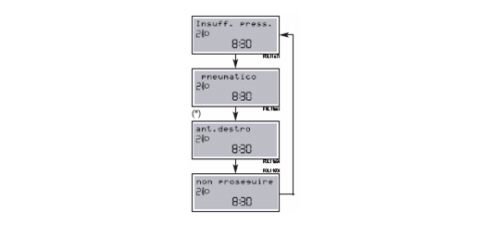
The instrument panel acquires these signals and manages the readings as described below.When the pressure value of one or more of the tyres exceeds the first CHECK level (nominal pressure - 0.3 bar when hot or - 0.45 when cold) (pressure above 3.2 bar), the general failure warning light comes on in the instrument panel and an alphanumerical message appears in the display e.g. "Check tyre pressure", accompanied by indication of tyre concerned: right front, left front, right rear or left rear. When the signalling cycle is over only the warning light remains activated in the panel until the correct pressure is restored.The warning cycle is repeated after 10 minutes (once).If the panel receives a signal that the pressure is below the WARNING level (nominal pressure -0.5 bar), the general failure warning light comes on and the message appears in the alphanumerical display "Insufficient tyre inflration pressure - right front - do not continue" accompanied by a buzzer dependent on the "priority 0" fault logic (See 5560).When the signalling cycle is over only the warning light remains activated in the panel until the correct pressure is restored.If there is a fault in the tyre pressure control unit, the "general failure" warning light comes on and the corresponding alphanumerical display shows "Tyre monitoring system not available".This takes place in the following cases:- fault in the control unit wiring and circuit;- no signal received from one or more sensors (sensor battery run down, faulty, broken)- TPMS control unit faulty- use of one or more wheels without sensors (e.g. with snow tyres).The display takes place about 12 minutes after the fault is detected.The display occurs when the CAN message is received if and only if the vehicle speed is above 20 km/h for longer than 30 seconds.The display takes place about 12 minutes after the fault is detected.If the Body Computer, correctly set, does not receive a message for longer than a minute, it sends the CPP fault signal which is displayed by the NQS.System not programmed: if the tyre pressure control unit has not been programmed, the following alphanumerical message is shown on the display "System Not Programmed".Tyre pressure control unit (cpp)
The CPP control unit is connected to the front wiring by means of a bridge.The receiver electronics is housed in a plastic casing that is not screened against RF.The fastenings allow the control unit to be fitted securely in position (preventing rotation).The CPP is an electronic component which, connected to the A-BUS serial line, manages the function of checking the tyre pressure and carries out a fault diagnosis via the K line.The receive| ... DATA ERROR - CROPPED TEXT | Ошибка данных - Текст обрезан ... |
|---|