The M32 manual gearbox is designed to be installed in front wheel drive systems with the engine tranversely mounted. The code M32 means that the gearbox has been designed to support a transmission with a maximum torque of 320 Nm.
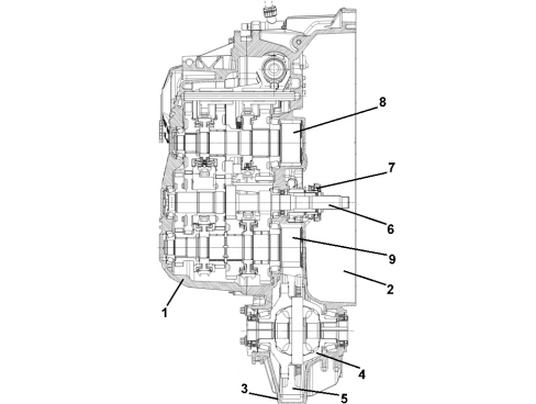
1. Gearbox casing2. Clutch casing3. Differential casing4. Differential internal casing5. Differential ring gear6. Main shaft (A)7. Clutch control coaxial actuator8. Layshaft (B)9. Second layshaft (C)The specific features are:- manual gearbox with fixed idler with six transmission ratios plus reverse;- all gears with synchromesh (including reverse);- toothed wheels with helical teeth;- three shafts, one input plus two secondary (upper and lower);- differential integrated in the gearbox casing;- dry weight 46.7 km;- activation by hydraulic clutch;- designed for matching with twin mass flywheel;- body divided into three sections to facilitate maintenance operations.
COMPOSITION OF THE GEARBOX
Inside the gearbox each transmission ratio is produced by means of a pair of gears that mesh constantly with one freewheeling on the respective shaft. Reverse gear is an exception and is produced by means of a train with three gears to reverse the direction of power.The main shaft receives the drive directly from the crankshaft; when a gear is selected, the torque is transferred, via the pair of gears for the speed selected, to the layshaft and, from there, to the fixed idler, connected to the differential.
Engagement diagram
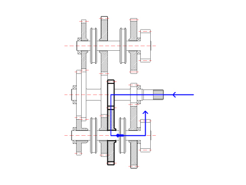
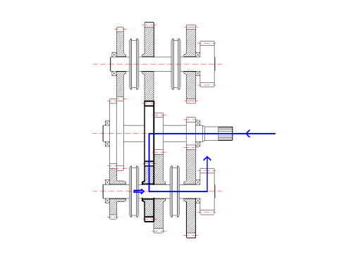
First and second speedFIRST SPEED ENGAGEMENT
SECOND SPEED ENGAGEMENT
In first speed the power enters the gearbox via the main shaft and is transmitted, through the fixed drive gear, to the driven gear for the first speed fitted in neutral on the lower layshaft. The activation of the synchronizer (for first and second speed) makes the toothed wheel form one piece with the layshaft and, by means of the fixed idler wheel, with the differential.By moving the synchronizer in the opposite direction, the driven gear for the second speed forms one piece with the layshaft; the second speed is produced in this way.Third and fourth speedTHIRD SPEED ENGAGEMENT
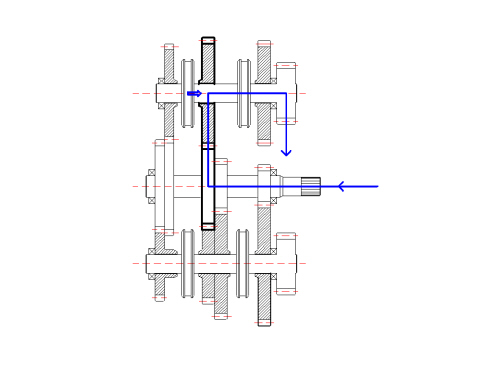
FIFTH SPEED ENGAGEMENT
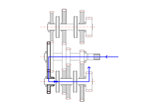
The power enters the gearbox via the main shaft and, by means of the fixed drive gear, is transferred to the driven gear, fitted on the upper layshaft; the activation of the synchronizer (for third and fourth speed) makes it possible to transfer the power to the toothed wheel for the fixed idler, also forming one piece with the differential ring gear, like the one on the lower shaft.Moving the synchronizer in the opposite direction produces the engagement of fourth speed.Fifth and sixth speedFIFTH SPEED ENGAGEMENT
SIXTH SPEED ENGAGEMENT
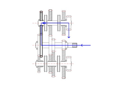
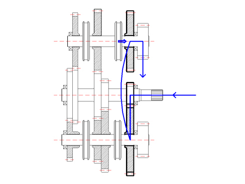
The power enters the gearbox via the main shaft and, by means of the fixed drive gear, is transferred to the driven gear, fitted on the lower layshaft; the activation of the synchronizer (for fifth and sixth speed) makes it possible to transfer the power to the toothed wheel for the fixed idler, also forming one piece with the differential ring gear.To engage sixth speed, the same synchronizer is activated in the opposite direction to previously.Reverse gearREVERSE GEAR ENGAGEMENT
The power entering the gearbox is transferred from the main shaft to the gear for first speed fitted on the lower layshaft; this gear acts as a free wheel because it transfers the power to the toothed wheel for reverse gear fitted on the upper layshaft with which it meshes; at the same time, this allows the reversal of the power. The synchronizer for reverse gear makes the wheel form one piece with the upper layshaft, transferring the power to the differential.
Toothed wheels
MATERIALS AND MACHINING: the toothed wheels are subjected to variable loads over a period of time which produce stresses and fatigue; for these reasons nickel chrome steel alloys are used which afford good mechanical resistance; after machining the toothed wheels firstly undergo a finishing process (grinding) and afterwards a heat treatment that improves their resistance properties to fatigue and wear (binding and tempering).SPECIFICATIONS: the toothed wheels used have helical teeth. The adoption of toothed wheels with helical teeth allows the transmission of higher torques compared with those of the same size with straight teeth; in addition, toothed wheels with helical teeth afford smoother and quieter operation; another important feature of the gears in the gearbox in question is the teeth with a high covering factor; several teeth (and not just one) are always meshed, with the advantage of smooth transmission.
Shafts
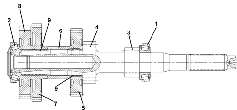
Main shaft (a)
1. Front bearing2. Rear bearing3. 1st speed gear4. 2nd speed gear5. 3rd-5th speed gear6. Spacer7. 4th speed gear8. 6th speed gear9. Needle bearingsSPECIFICATIONS: the gearbox input shaft has all the toothed wheels forming one piece: in particular the toothed wheels for first and second are directly on the part, i.e. they physically form part of the shaft as they are produced through mechanical machining processes, whilst the others for third and fifth speeds and fourth and sixth are fitted by means of splining in the actual shaft and are an interference with on the shaft itself.The gearbox main shaft is supported by two conical roller bearings.Layshaft (b)
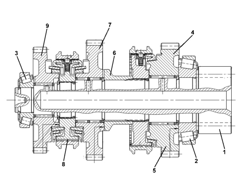
1. Pinion2. Front bearing3. Rear bearing4. Reverse gear5. Reverse single cone synchronizer6. Spacer7. 3rd speed gear8. 3rd-4th speed double cone synchronizer9. 4th speed gearSPECIFICATIONS: the upper layshaft supports the wheels that produce third and fourth forward speeds and reverse; these wheels are all fitted in neutral on roller bearings.There are two synchronizers: one, triple cone synchronizer, designated to form one piece between the wheels for third or fourth speed with the shaft, the other single cone synchronizer, for reverse.There is a toothed wheel on the shaft that transfers the power to the differential ring gear.The shaft is supported by two conical roller bearings.Second layshaft (c)
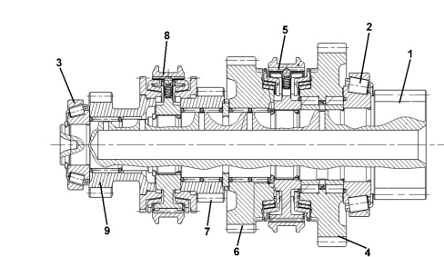
1. Pinion2. Front bearing3. Rear bearing4. 1st speed gear5. 1st-2nd speed triple cone synchronizer6. 2nd speed gear7. 5th speed gear8. 5th-6th speed single cone synchronizer9. 6th speed gearThe wheels that produce first, second, fifth and sixth forward speeds are fitted on this shaft; the toothed wheel for first speed is also involved in producing reverse.The shaft is supported by two conical roller bearings.
Synchronizers
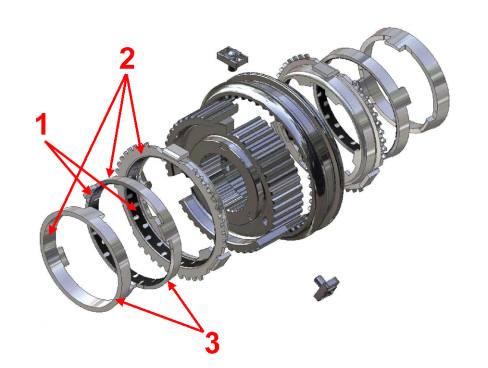
The diagram shows the exploded view of the synchronizer for third and fourth speeds. It is the triple cone type to ensure optimum continuity and smooth transfer of torque between the shafts.
1. On the synchronizer for third and fourth speeds, two of the three cones contain a carbon friction ring2. The synchronizer for first and second speeds also has this friction ring on all three cones.3. The synchronizers for fifth and sixth speeds and reverse are the single cone type (they do not have the first two cones).In the case of the synchronizer for fifth and sixth speeds and reverse, given the lesser torque produced by the actual gearbox, a single cone synchronizer is used.
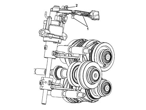
Gear selector and engagement assembly
The gear selector and engagement assembly comprises a kinematic arrangement connected, by means of cables, to the control lever in the passenger compartment.The kinematic arrangement has two possible movements: vertical travel designed to select the synchronizer; movement in a rotary direction is designed to activate the fork for the synchronizer.