194002219 - INTRODUCTION - EXTERIOR LIGHTING
INTRODUCTION
The vehicle exterior lighting system has been designed and produced with two objectives in mind:- guaranteeing maximum efficiency with regard to the international regulations that define the lighting technology specifications for the various components;- being integrated with the design of the vehicle so that the various components enhance the image.The side light, dipped headlamp, main beam hedlamp and direction indicator are in a single front unit, managed separately.The fog light, on the other hand, has its own lamp.The vehicle components and their location are illustrated below.
FRONT LIGHT CLUSTER
The light cluster is composed as follows:

Connector pin out
The pin out for the connector is illustrated in the diagram below.
| Pin | Function |
|---|---|
| 1 | Dipped headlight |
| 3 | Main beam headlight |
| 4 | Side light |
| 5 | Direction indicator |
| 6 | Headlight alignment motor (+) |
| 7 | Headlight alignment motor (signal) |
| 8 | Headlight alignment motor (-) |
| 14 | Bulb earth |
FOG LIGHTS
The fog light basically consists of a single block located in the special housings in the front bumper; it comprises a solid body and a cover with a connector through which it is possible to gain access if the bulb needs replacing. A special adjustment screw makes it possible to adjust the light beam manually.The lamp contains the following type of bulb:- H 1.55 W bulbREAR LIGHT CLUSTER
The rear light cluster consists of two parts: one fixed part located directly on the bodywork and one moving part located on the tailgate. The light cluster carries out the following functions:- Side light- Brake light- Reversing light- Direction indicator- Brake light- Rear fog lampThe fixed part of the rear light cluster contains the following bulbs: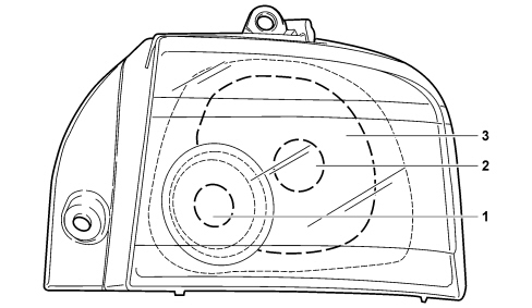

| Pin | Function |
|---|---|
| 1 | Earth |
| 2 | Side light |
| 3 | Brake light |
| 4 | Direction indicator |


| Pin | Function |
|---|---|
| 1 | Earth |
| 2 | Rear fog lamp |
| 3 | Reverse gear |
DIRECTION INDICATORS SIDE REPEATER
The side light is illustrated in the diagram.
NUMBER PLATE LIGHT
The number plate light function is achieved by means of two lights fitted using a metal clip and a catch projection fastened to the trim. Each light has a bulb on the connector.The bulbs are:- C 5 W bulb for rear number plate lights functionTo replace the bulb, extract the entire casing by hand releasing it from the clip, release the connector from the housing and keep the bulb.COURTESY (PUDDLE) LIGHTS
The switching on of the various lamps located in the lower part of the front doors is managed by the signals coming from microswitches which send an earth signal to the Body Computer which notifies the driver''s door and passenger doors nodes, via the CAN, of the door status.Opening one of the doors causes the lights to come on for a maximum period of 3 minutes. When this timed period expires it will only be possible to reactivate the puddle lights after one of the doors has been reopened once again.Closing both doors causes the lights to go out immediately.ADDITIONAL BRAKE LIGHT
The additional side light is illustrated in the diagram.
LIGHTS OPERATION
Left control panel
The left control panel is located to the left of the steering wheel and it carries out the following functions: fog lights, rear fog lamps, parking lights, headlamp alignment adjustment and dusk sensor sensitivity settings.The control panel is illustrated in the diagram.
| On versions with gas discharge headlamps, the headlamp alignment adjustment is automatic therefore the button in the left control panel is replaced by a plug. |
| Pin | Function |
|---|---|
| 1 | Negative signal from rear fog lamps control |
| 2 | Fog lights control negative signal |
| 8 | Negative signal from MODE/DIM "-" control |
| 10 | Parking lights control negative signal |
| 11 | Earth |
| 12 | Analogue signal from MODE/DIM "+" control |
| 17 | Ideogram light dimmed supply |
| 18 | Analogue signal from headlamp alignment control |
Side lights and number plate light
When the ring nut on the left steering column switch unit lever is turned once, the side lights/no. plate lights circuit is enabled.The switching on of the side lights is managed by the Body Computer: the side lights control function is activated through the enablement signals with the key inserted and turned to the ON position and the specific command from the steering column switch unit.The activation and/or deactivation information is sent via the CAN and the side lights warning light in the instrument panel is switched on together with the activation of the serigraphy lighting.The operation of the parking lights function, on the other hand, is different; in this case the key should be extracted (STOP) or turned to the OFF position and the PARK button in the panel on the left side of the steering wheel pressed enabling he parking lights function. The engagement of the above control is signalled by a roger beep.By turning the left steering column switch unit lever (in the same way as for activating the direction indicator) the activation of the lights on the left side of the vehicle can be selected; with the steering column switch unit lever turned completely towards the right the lights on the right side of the vehicle come on and with the steering column switch unit lever in the centre position the lights on both sides of the vehicle come on.Dusk sensor
The side lights and the dipped headlamps can also be turned on automatically if the AUTO function is set on the steering column switch unit. The dusk sensor, located in the electrochromic mirror, is an infrared device that works on three sensitivity settings duely shownn in the display; the default setting is the second level, but it is possible to alter the sensitivity (from 1 to 3) using the "Mode +" and "Mode -" buttons located in the panel to the left of the steering wheel.Dusk/rain sensor
Follow me home
The "Follow me home" function allows the dipped headlamps and the side lights to remain on even after the engine has been switched off (key extracted - STOP - or turned to OFF) for a period of 30 seconds or multiples thereof. The lights are activated by operating the light flasher stalk within 2 minutes of switching the engine off: each time the lever is operated, the period for which the lights are on is increased by 30 seconds to a maximum of 210 seconds. The function is excluded if the ignition is turned ON or if the flasher lever is operated for more than two seconds.Dipped beams
The vehicle is equipped with two dipped beams in the headlamps.When the ring nut on the left steering column switch unit lever is turned twice, the dipped headlamps circuit is enabled.The switching on of the dipped headlamps is managed by the Body Computer: the dipped headlamps control function is activated through the enablement signals with the key inserted and turned to the ON position and the specific command from the steering column switch unit.With the dipped headlamps on, the simultaneous presence of the main beam and fog lights commands disables the dipped headlamps. The subsequent deactivation of one of these two commands, with the dipped headlamps control still on, means that the dipped headlamps will be turned back on again.Main beams
The vehicle is equipped with two main beams in the headlamps.There are two different types of operation for the main beams:- when the dipped beams are on, by pulling the left steering column switch unit lever toward the dashboard (2nd unstable position);- in flashing mode, irrespective of wheel position, by pulling the left lever towards the steering wheel (1st unstable position);A special relay - managed by the Body Computer - controls the engagement of the main beam headlamps using the enablement signals with the ignition ON and the specific steering column switch unit command signal.The activation and/or deactivation information acquired is sent via the CAN to switch the main beam headlamps warning light in the instrument panel on or off.| for legal reasons, if the dusk sensor is activated, only the flasher can be operated and the main beams cannot be turned on permanently; the AUTO function must be switched off in order to activate these lights. |
Brake lights
The vehicle is equipped with brake lights and a third additional brake light on the inner top part of the boot.They are activated by a switch located directly on the brake pedal each time it is pressed.The brake lights management switch on the pedal comprises two contacts: the first "N.A." type recognizes the position of the pedal in a state other than the rest position (pedal pressed); the second "N.C." type recognizes the state of the pedal in the rest position.The enablement for the activation of the brake lights is given by the "N.A.". contact which sends information to the engine management control unit and to the ABS/ESP control unit; the "N.C." type switch is used by the engine management control unit for the Cruise Control function in particular.
| ... DATA ERROR - CROPPED TEXT | Ошибка данных - Текст обрезан ... |
|---|