194002383 - 1064A TURBOCHARGER ASSEMBLY
COMPONENT DESCRIPTIONS
GARRET GT1749V TURBOCHARGER
It has variable geometry and is connected to the exhaust manifold; its purpose is to increase the volumetric output of the engine.This variable geometry turbocharger consists of:
- a centrifugal compressor
- a turbine
- a series of moving vanes
- a pneumatic actuator for operating the moving vanes.

This variable geometry turbocharger makes it possible to:
- increase the speed of the exhaust gases in the turbine at low engine speeds
- slow down the speed of the exhaust gases in the turbine at high speeds.
Controlling the speed (kinetic energy) of the exhaust gases makes it possible to produce:
- greater engine torque at low speeds
- greater maximum power at high speeds.
Operation and high rotation speeds
If the engine rotation speed increases, the kinetic energy of the exhaust gases also gradually increases.As a result the speed of the turbine (1) increases and consequently the supercharging pressure which also acts on the actuator (3).The actuator (3), controlled by the solenoid, operates the opening of the moving vanes (2) via a rod, until the fully open position is reached.There is therefore an increase in the sections and consequently a slowing down in the flow of the exhaust gases passing through the turbine (1) at speeds which are the same as or lower than those for the low speed conditions.The speed of the turbine (1) decreases and settles down at a suitable rate for the correct operation of the engine at high speeds.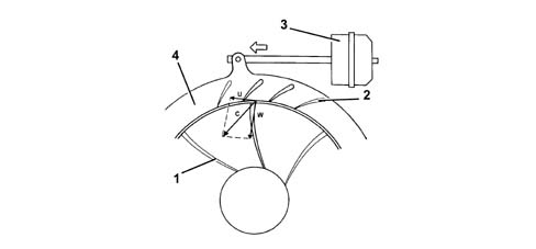
Operation at low rotation speeds
When the engine rotation speed is low, the exhaust gases possess little kinetic energy: under these circumstances, a conventional turbine would rotate slowly, supplying a limited supercharging pressure.In a variable geometry turbine (1), on the other hand, the moving vanes (2) are in the maximum closure position and the small sections between the vanes increase the speed (C) of the intake gases.Increased intake speeds result in greater peripheral speeds (U) for the turbine and consequently the compressor.The speed of the gases inside the impeller is shown by the vector (W).