194000344 - 1064A27 PIPE BETWEEN VACUUM RESERVOIR AND ACTUATOR CONTROL SOLENOID VALVE - R.R.


| Component | Fastening | dia | Value (daNm) | Validity |
|---|---|---|---|---|
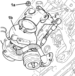
| Turbocharger and exhaust manifold assembly | Nut | M8 | (cylinder head side) 1.8 - 2.2 | 1.9 JTD 16v |

| Component | Fastening | dia | Value (daNm) | Validity |
|---|---|---|---|---|
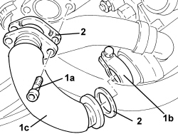
| Exhaust gas/water heat exchanger for E.G.R. system | Bolt | M8 | (exhaust manifold side) 2.3 - 2.8 | 1.9 JTD 16v2.4 JTD 20v |
| Component | Fastening | dia | Value (daNm) | Validity |
|---|---|---|---|---|
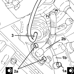
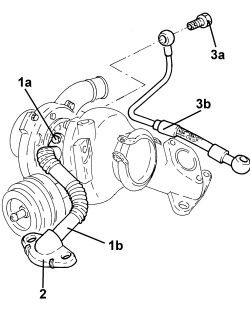
| Engine oil supply pipe to turbocharger | Connector | M12 | (engine crankcase side) 2.2 - 2.7 | 1.9 JTD 16v1.9 JTD 8v |
| Component | Fastening | dia | Value (daNm) | Validity |
|---|---|---|---|---|
| Engine oil supply pipe from turbocharger | Bolt | M8 | (engine crankcase side) 2.2 - 2.7 | 1.9 JTD 16v1.9 JTD 8v |