194002127 - 1016E10 SINGLE CYLINDER HEAD, REMOVED - OVERHAUL
| Tool | Description | Function | Validity |
|---|---|---|---|
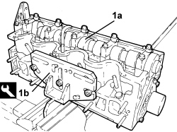
| 1860470001 | Support | Overhaul cylinder head |
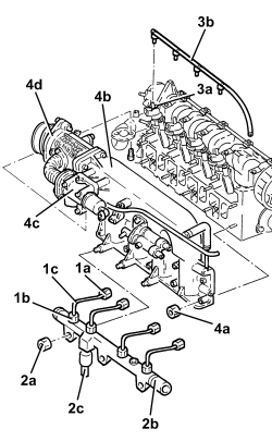
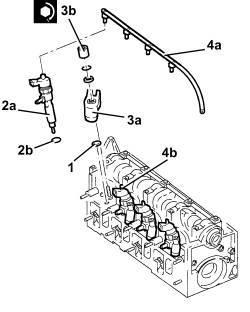
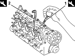
| Use new pipes from the fuel manifold to the injectors when refitting. |
| Measurement | Value | Validity |
|---|---|---|
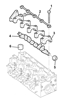
| Camshaft end float | 0.100 - 0.230 mm | 1.9 JTD 8V |
| Tool | Description | Function | Validity |
|---|---|---|---|
| 1820257000 | Support | Valve support | 1.9 JTD 8V |
| Tool | Description | Function | Validity |
|---|---|---|---|
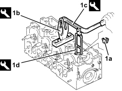
| 1821058000 | Lever | Valve spring compression lever | 2.21.9 JTD 8V |
| Tool | Description | Function | Validity |
|---|---|---|---|
| 1821205000 | Chamber | Removing/refitting valves | 1.9 JTD 8V |
| Tool | Description | Function | Validity |
|---|---|---|---|
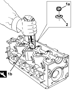
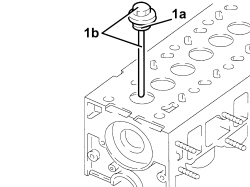
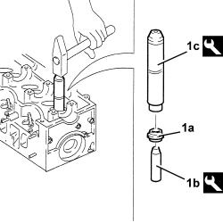
| 1870894000 | Extractor | Valve guide oil seal extraction | 1.9 JTD 8V |
| Measurement | Value | Validity | ||
|---|---|---|---|---|
| Cylinder head lower surface flatness | 0.1 mm | 1.9 JTD 8V2.4 JTD 20V | ||
| Measurement | Value | Validity | ||
|---|---|---|---|---|
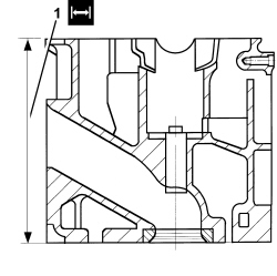
| Cylinder head lower plane minimum permitted height | 140.85 - 141.15 mm | 1.9 JTD 8V | ||
| Measurement | Value | Validity |
|---|---|---|
| Exhaust/inlet valve stem diameter | 7.974 - 7.992 mm | 1.9 JTD 8V |
| Measurement | Value | Validity |
|---|---|---|
| Tappet rod outer diameter | 36.975 - 36.991 mm | 1.9 JTD 8V |
| Measurement | Value | Validity |
|---|---|---|
| Tappet rod housing diameter | 37.010 - 37.030 mm | 1.9 JTD 8V |
| Measurement | Value | Validity |
|---|---|---|
| Valve spring free length | 53.9 mm | 1.9 JTD 8V |
| Measurement | Value | Validity |
|---|---|---|
| Length of valve springs under a load of 21.5 - 24.5 daN | 43.12 mm | 1.9 JTD 8V |
| Measurement | Value | Validity |
|---|---|---|
| Length of valve springs under a load of 43.6 - 48.6 daN | 32.34 mm | 1.9 JTD 8V |
| Measurement | Value | Validity |
|---|---|---|
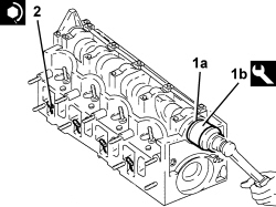
| Camshaft journal diameter | 26.000 - 26.015 mm | 1.9 JTD 8V |
| Measurement | Value | Validity |
|---|---|---|
| Nominal inlet cam lift | 8.5 mm | 1.9 JTD 8V |
| Measurement | Value | Validity |
|---|---|---|
| Nominal exhaust cam lift | 9.0 mm | 1.9 JTD 8V |
| Component | Fastening | dia | Value (daNm) | Validity |
|---|---|---|---|---|
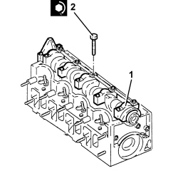
| Camshaft caps | Bolt | M7 | (cylinder head side) 1.3 - 1.6 | 1.9 JTD 8V |
| Measurement | Value | Validity |
|---|---|---|
| Diameter of camshaft mounts | 26.045 - 26.070 mm | 1.9 JTD 8V |
| Measurement | Value | Validity |
|---|---|---|
| Inlet valve seat outer diameter | 36.039 - 36.064 mm | 1.9 JTD 8V |
| Measurement | Value | Validity |
|---|---|---|
| Exhaust valve seat outer diameter | 35.039 - 35.064 mm | 1.9 JTD 8V |
| Measurement | Value | Validity |
|---|---|---|
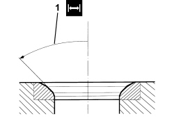
| Valve seat band angle in contact with valve | 45° +/- 20’ | 1.9 JTD 8V |
| Measurement | Value | Validity |
|---|---|---|
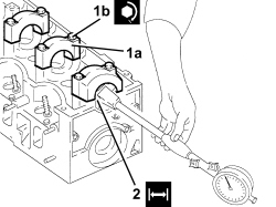
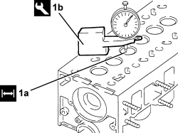
| Valve recess in relation to cylinder head plane | 0.1 - 0.5 mm | 1.9 JTD 8V |
| Tool | Description | Function | Validity |
|---|---|---|---|
| 1820253000 | Dial gauge support | Measure the piston projection/valve recess in relation to the cylinder head plane | 1.9 JTD 8V |
| Tool | Description | Function | Validity |
|---|---|---|---|
| 1860814001 | Drift | Fit valve oil seal | 2.21.9 JTD 8V |
| Tool | Description | Function | Validity |
|---|---|---|---|
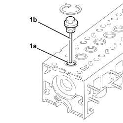
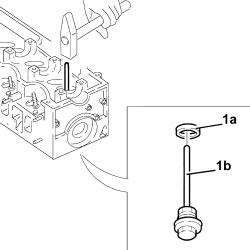
| 1821178000 | Fitting tool | Valve guide oil seal fitting | 1.9 JTD 8V |
| Tool | Description | Function | Validity |
|---|---|---|---|
| 1820257000 | Support | Valve support | 1.9 JTD 8V |
| Tool | Description | Function | Validity |
|---|---|---|---|
| 1821058000 | Lever | Valve spring compression lever | 2.21.9 JTD 8V |
| Tool | Description | Function | Validity |
|---|---|---|---|
| 1821205000 | Chamber | Removing/refitting valves | 1.9 JTD 8V |
| Apply LOCTITE to the contact surfaces with the head for the 1st and 5th camshaft caps. |
| Component | Fastening | dia | Value (daNm) | Validity |
|---|---|---|---|---|
| Camshaft caps | Bolt | M7 | (cylinder head side) 1.3 - 1.6 | 1.9 JTD 8V |
| Component | Fastening | dia | Value (daNm) | Validity |
|---|---|---|---|---|
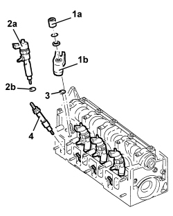
| Heater plugs | - | M12 | 1.3 ÷ 1.6 | 1.9 JTD 8v |
| Component | Fastening | dia | Value (daNm) | Validity |
|---|---|---|---|---|
| Injector brackets | Nut | M8 | 2.7 ÷ 3.3 | 1.9 JTD 8V |
| Component | Fastening | dia | Value (daNm) | Validity |
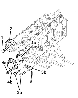
|---|---|---|---|---|
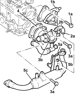
| Water pump | Bolt | M8 | (cylinder head side) 2.3 - 2.8 | 1.9 JTD 8V1.9 JTD 16V |
| Component | Fastening | dia | Value (daNm) | Validity |
|---|---|---|---|---|
| Driven toothed pulley | Bolt | M12 | (camshaft side) 2.9 - 3.2 + 40° | 1.9 JTD 8V1.9 JTD 16V |
| Measurement | Value | Validity |
|---|---|---|
| Inlet valves clearance in closed position | 0.25 - 0.35 mm | 1.9 JTD 8V |
| Measurement | Value | Validity |
|---|---|---|
| Exhaust valves clearance in closed position | 0.30 - 0.40 mm | 1.9 JTD 8V |
| Tool | Description | Function | Validity |
|---|---|---|---|
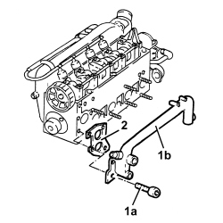
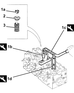
| 1820262000 | Lever | Lower tappets | 1.9 JTD 8V |
| Tool | Description | Function | Validity |
|---|---|---|---|
| 1860724001 | Lever | Keep valve tappets lowered | 1.9 JTD 8V |
| Tool | Description | Function | Validity |
|---|---|---|---|
| 1820262000 | Lever | Lower tappets | 1.9 JTD 8V |
| Tool | Description | Function | Validity |
|---|---|---|---|
| 1860724001 | Lever | Keep valve tappets lowered | 1.9 JTD 8V |
| Component | Fastening | dia | Value (daNm) | Validity |
|---|---|---|---|---|
| Thermostat | Bolt | M8 | (cylinder head side) 2.3 - 2.8 | 1.9 JTD 8V |
| Component | Fastening | dia | Value (daNm) | Validity |
|---|---|---|---|---|
| Vacuum unit | Bolt | M8 | (cylinder head side) 2.7 - 3.3 | 1.9 JTD 8V |
| Component | Fastening | dia | Value (daNm) | Validity |
|---|---|---|---|---|
| Pipes from fuel manifold to injectors | Connector | M12 | (injector side) 2.2 - 2.4 | 1.9 JTD 8V |
| Component | Fastening | dia | Value (daNm) | Validity |
|---|---|---|---|---|
| Pipes from fuel manifold to injectors | Connector | M14 | (fuel manifold side) 2.2 - 2.4 | 1.9 JTD 8V |