194002180 - 1060G90 SYSTEM CABLE LOOM - R.R.
 Removing
		(
		Refitting
Removing
		(
		Refitting )
	- Position the vehicle on a lift.    Op. 1016A10 SOUND-PROOFING COVER - R.R    Op. 5530B10 BATTERY - R+R    Op. 5530B52 BATTERY SUPPORT/DRIP TRAY - R.R    Op. 1048A10 AIR FILTER ASSEMBLY - R.R.    Op. 4450B04 RIGHT FRONT WHEEL - R.R    Op. 7055B66 ENGINE COMPARTMENT DUST COVER IN RIGHT FRONT WHEEL ARCH - R.R.    Op. 7055B91 RIGHT FRONT WHEEL ARCH LINER - R.R.    Op. 7055B54 UNDER ENGINE PROTECTION/GUARD - R.R.1. Disconnect the electrical connections from the diesel electronic injection system control unit.
		)
	- Position the vehicle on a lift.    Op. 1016A10 SOUND-PROOFING COVER - R.R    Op. 5530B10 BATTERY - R+R    Op. 5530B52 BATTERY SUPPORT/DRIP TRAY - R.R    Op. 1048A10 AIR FILTER ASSEMBLY - R.R.    Op. 4450B04 RIGHT FRONT WHEEL - R.R    Op. 7055B66 ENGINE COMPARTMENT DUST COVER IN RIGHT FRONT WHEEL ARCH - R.R.    Op. 7055B91 RIGHT FRONT WHEEL ARCH LINER - R.R.    Op. 7055B54 UNDER ENGINE PROTECTION/GUARD - R.R.1. Disconnect the electrical connections from the diesel electronic injection system control unit.| Description | Connector | |
|---|---|---|
| 1 | Engine management control unit | See M010 ENGINE MANAGEMENT CONTROL UNIT | 

| Description | Connector | |
|---|---|---|
| 1 | Air conditioning compressor engagement electro-magnet | See L020 AIR CONDITIONING COMPRESSOR ENGAGEMENT ELECTRO-MAGNET | 

| Description | Connector | |
|---|---|---|
| 1 | 4 stage pressure switch | See K010 4 STAGE PRESSURE SWITCH | 


| Description | Connector | |
|---|---|---|
| 1 | Engine cables/engine services cable coupling | See D029 ENGINE CABLES/ENGINE SERVICES CABLE COUPLING | 
| Description | Connector | |
|---|---|---|
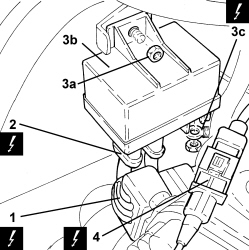
| 2 | Heater plugs control unit | See M015 HEATER PLUGS CONTROL UNIT | 
| Description | Connector | |
|---|---|---|
| 3c | Heater plugs control unit | See M015 HEATER PLUGS CONTROL UNIT | 
| Description | Connector | |
|---|---|---|
| 4 | Timing sensor | See K047 TIMING SENSOR | 

| Description | Connector | |
|---|---|---|
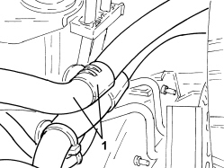
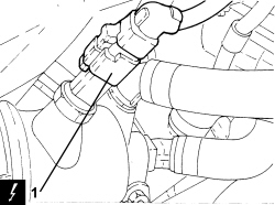
| 1 | Fuel temperature sensor and heating resistance | See K100 TEMPERATURE SENSOR AND HEATING RESISTANCE | 
| Description | Connector | |
|---|---|---|
| 2 | Water in diesel filter sensor | See K031 WATER IN DIESEL FILTER SENSOR | 

| Description | Connector | |
|---|---|---|
| 1 | EGR solenoid valve | See L030 EGR SOLENOID VALVE | 

| Description | Connector | |
|---|---|---|
| 1 | Engine coolant temperature sensor/sender unit | See K036 ENGINE COOLANT TEMPERATURE SENSOR/SENDER UNIT | 

| Description | Connector | |
|---|---|---|
| 1 | Integrated throttle casing actuator | See N075 INTEGRATED THROTTLE CASING ACTUATOR | 
| Description | Connector | |
|---|---|---|
| 2 | Fuel pressure sensor | See K083 FUEL PRESSURE SENSOR | 

| Description | Connector | |
|---|---|---|
| 1 | Downstream catalytic converter temperature sensor | See K188 | 

| Description | Connector | |
|---|---|---|
| 1 | Injector | See N070 INJECTOR | 

| Description | Connector | |
|---|---|---|
| 2 | Fuel pressure regulator on pressure pump | See N077 FUEL PRESSURE REGULATOR | 
| Description | Connector | |
|---|---|---|
| 2 | Fuel pressure regulator on rail | See N087 FUEL PRESSURE REGULATOR ON RAIL | 

| Description | Connector | |
|---|---|---|
| 1b | Starter motor | See A020 STARTER MOTOR | 

| Description | Connector | |
|---|---|---|
| 1 | Insufficient engine oil pressure sensor (switch) | See K030 INSUFFICIENT ENGINE OIL PRESSURE SENSOR | 

| Description | Connector | |
|---|---|---|
| 1 | Engine rpm sensor | See K046 RPM SENSOR | 
| Description | Connector | |
|---|---|---|
| 2 | Engine oil level sensor | See K032 ENGINE OIL LEVEL SENSOR | 


 Refitting
		(
		Removing
Refitting
		(
		Removing )
	- Place the system cable loom in its housing and secure it.- Connect the earth lead to the alternator and secure it using the nut.- Connect the electrical connection to the engine oil level sensor.- Connect the electrical connection for the engine rpm sensor.- Connect the electrical connection to the engine oil pressure warning light switch.- Connect the earth lead to the starter motor and secure it using the nut.- Connect the electrical connection to the fuel pressure regulator on the injector single manifold.- Connect the electrical connection to the fuel pressure regulator on the pressure pump.- Place the fuel return manifold pipe in its housing and secure it using the bolts.- Place the electrical wiring in position and fasten it using the bolts.- Connect the electrical connections to the injectors.- Connect the electrical connection to the exhaust gas temperature sensor to the particle filter.- Connect the electrical connection to the fuel pressure sensor.- Connect the electrical connection to the throttle casing.- Connect the electrical connection to the engine coolant temperature sensor.- Connect the electrical connection for the pressure relief sensor.- Connect the electrical connection for the E.G.R. solenoid valve.- Connect the electrical connection to the water presence sensor on the fuel filter.- Connect the electrical connection to the fuel filter.- Connect the intermediate coupling for the cam angle sensor.- Connect the electrical connections to the heater plugs control unit then place it in its housing and secure it using the nut.- Connect the electrical connections to the heater plugs control unit.- Connect the intermediate engine wiring coupling.- Place the electrical wiring in position and fasten it to the bands.- Connect the earth lead and tighten the nut.- Connect the electrical connection to the air conditioning system multi-stage pressure switch.- Connect the air conditioning compressor electrical connection.- Connect the electrical connections to the diesel electronic injection system control unit.    Op. 7055B54 UNDER ENGINE PROTECTION/GUARD - R.R.    Op. 7055B91 RIGHT FRONT WHEEL ARCH LINER - R.R.    Op. 7055B66 ENGINE COMPARTMENT DUST COVER IN RIGHT FRONT WHEEL ARCH - R.R.    Op. 4450B04 RIGHT FRONT WHEEL - R.R    Op. 1048A10 AIR FILTER ASSEMBLY - R.R.    Op. 5530B52 BATTERY SUPPORT/DRIP TRAY - R.R    Op. 5530B10 BATTERY - R+R    Op. 1016A10 SOUND-PROOFING COVER - R.R- Remove the vehicle from the lift.
		)
	- Place the system cable loom in its housing and secure it.- Connect the earth lead to the alternator and secure it using the nut.- Connect the electrical connection to the engine oil level sensor.- Connect the electrical connection for the engine rpm sensor.- Connect the electrical connection to the engine oil pressure warning light switch.- Connect the earth lead to the starter motor and secure it using the nut.- Connect the electrical connection to the fuel pressure regulator on the injector single manifold.- Connect the electrical connection to the fuel pressure regulator on the pressure pump.- Place the fuel return manifold pipe in its housing and secure it using the bolts.- Place the electrical wiring in position and fasten it using the bolts.- Connect the electrical connections to the injectors.- Connect the electrical connection to the exhaust gas temperature sensor to the particle filter.- Connect the electrical connection to the fuel pressure sensor.- Connect the electrical connection to the throttle casing.- Connect the electrical connection to the engine coolant temperature sensor.- Connect the electrical connection for the pressure relief sensor.- Connect the electrical connection for the E.G.R. solenoid valve.- Connect the electrical connection to the water presence sensor on the fuel filter.- Connect the electrical connection to the fuel filter.- Connect the intermediate coupling for the cam angle sensor.- Connect the electrical connections to the heater plugs control unit then place it in its housing and secure it using the nut.- Connect the electrical connections to the heater plugs control unit.- Connect the intermediate engine wiring coupling.- Place the electrical wiring in position and fasten it to the bands.- Connect the earth lead and tighten the nut.- Connect the electrical connection to the air conditioning system multi-stage pressure switch.- Connect the air conditioning compressor electrical connection.- Connect the electrical connections to the diesel electronic injection system control unit.    Op. 7055B54 UNDER ENGINE PROTECTION/GUARD - R.R.    Op. 7055B91 RIGHT FRONT WHEEL ARCH LINER - R.R.    Op. 7055B66 ENGINE COMPARTMENT DUST COVER IN RIGHT FRONT WHEEL ARCH - R.R.    Op. 4450B04 RIGHT FRONT WHEEL - R.R    Op. 1048A10 AIR FILTER ASSEMBLY - R.R.    Op. 5530B52 BATTERY SUPPORT/DRIP TRAY - R.R    Op. 5530B10 BATTERY - R+R    Op. 1016A10 SOUND-PROOFING COVER - R.R- Remove the vehicle from the lift.