194000547 - 4410D10 FRONT SUSPENSION FRAME - R+R
| Description | Connector | |
|---|---|---|
| - | Battery | See A001 BATTERY |
| The bolt is the pre-treated type and it therefore cannot be reused when refitting. |
| Tool | Description | Function | Validity |
|---|---|---|---|
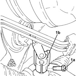
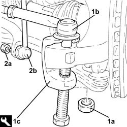
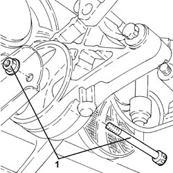
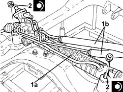
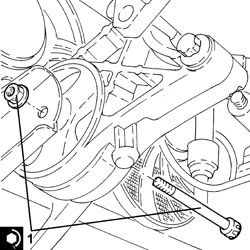
| 1871000700 | Extractor | Extracting steering rod from steering knuckle |
| Description | Connector | |
|---|---|---|
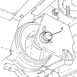
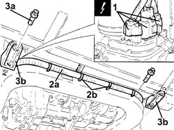
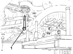
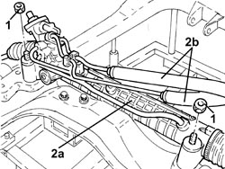
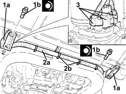
| 1 | Electric steering control unit | See M086 ELECTRIC STEERING CONTROL UNIT |
| The version with ABS is shown in the diagram. The version with ESP comes with the three electrical connections indicated plus a fourth electrical connection with wiring for connection to the steering angle sensor. |
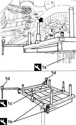
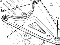
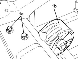
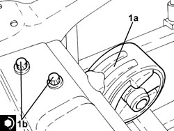
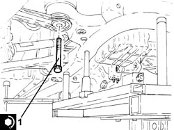
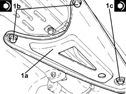
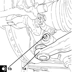
| Fit the guide pins (arrowed) into the front suspension frame body. |
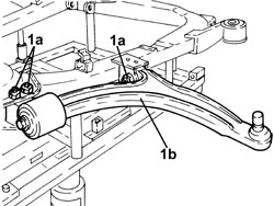
| The two locating pins (1d) must be lowered onto the underbody during the dismantling. |
| Tool | Description | Function | Validity |
|---|---|---|---|
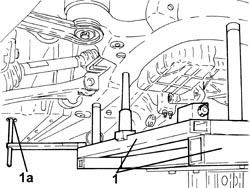
| 1870835001 | Hydraulic lift | Supporting front suspension frameRear suspension crossmember support |
| Tool | Description | Function | Validity |
|---|---|---|---|
| 2000001700 | Support | Front suspension frame/rear suspension crossmember support |
| Tool | Description | Function | Validity |
|---|---|---|---|
| 2000001800 | Support | Supporting front suspension frame |
| Tighten the above bolts with the wheels on the ground and the vehicle loaded to the theoretical design load. |
| Component | Fastening | dia | Value (daNm) | Validity |
|---|---|---|---|---|
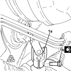
| Lower reaction rod for gearbox | Bolt | M10 | (front suspension frame side) 5.5 ÷ 6.5 |
| Component | Fastening | dia | Value (daNm) | Validity |
|---|---|---|---|---|
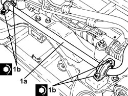
| Power assisted steering box | Nut (to replace) | M12 | (chassis side) 4.1 - 5.0 + 45° |
| Component | Fastening | dia | Value (daNm) | Validity |
|---|---|---|---|---|
| Front suspension anti-roll bar | Bolt | M8 | (chassis side) 1.8 - 2.2 |
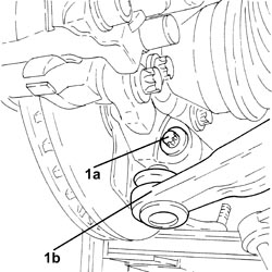
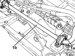
| During refitting, remove both locating pins (1a), which must fit into the holes in the underbody during assembly. |
| Component | Fastening | dia | Value (daNm) | Validity |
|---|---|---|---|---|
| Front suspension frame | Front-rear bolts (to replace) | M12 | (bodyshell side) 9.0 - 11.0 + 90° |
| Component | Fastening | dia | Value (daNm) | Validity |
|---|---|---|---|---|
| Underbody reinforcements | Inner bolt (to replace) | M12 | (bodyshell side) 8.1 - 9.9 + 45° |
| Component | Fastening | dia | Value (daNm) | Validity |
|---|---|---|---|---|
| Underbody reinforcements | Outer bolt (to replace) | M10 | (bodyshell side) 5.0 - 6.1 + 45° |
| Component | Fastening | dia | Value (daNm) | Validity |
|---|---|---|---|---|
| Underbody reinforcements | Bolt (to be replaced) | M12 | (front suspension frame side) 9.0 - 11.0 + 90° |
| Tool | Description | Function | Validity |
|---|---|---|---|
| 1870835001 | Hydraulic lift | Supporting front suspension frameRear suspension crossmember support |
| Tool | Description | Function | Validity |
|---|---|---|---|
| 2000001700 | Support | Front suspension frame/rear suspension crossmember support |
| Tool | Description | Function | Validity |
|---|---|---|---|
| 2000001800 | Support | Supporting front suspension frame |
| Component | Fastening | dia | Value (daNm) | Validity |
|---|---|---|---|---|
| Engine cooling radiator supports | Bolt | - | (front suspension frame side) 1.5 |
| Component | Fastening | dia | Value (daNm) | Validity |
|---|---|---|---|---|
| Flexible mounting for left side engine support | Bolt | M12 | (front suspension frame side) 7.5 ÷ 8.5 |
| Component | Fastening | dia | Value (daNm) | Validity |
|---|---|---|---|---|
| Lower reaction rod for gearbox | Bolt | M12 | (bracket side on gearbox) 7.5 - 8.5 |
| Component | Fastening | dia | Value (daNm) | Validity |
|---|---|---|---|---|
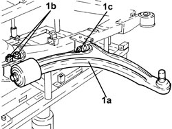
| Front suspension lower track control arm | Bolt (to be replaced) | M10 | (steering knuckle side) 2.7 - 3.3 + 60° |
| Component | Fastening | dia | Value (daNm) | Validity |
|---|---|---|---|---|
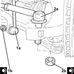
| Front suspension anti-roll bar joint | Nut | M12 | (anti-roll bar side) 6.0 - 7.0 |
| Component | Fastening | dia | Value (daNm) | Validity |
|---|---|---|---|---|
| Steering rods | Nut | M12 | (steering knuckle side) 3.0 - 4.0 |
| Component | Fastening | dia | Value (daNm) | Validity |
|---|---|---|---|---|
| Steering column | Bolt (to be replaced) | M8 | (power assisted steering box side) 2.3 - 2.8 |
| This operation prevents torsional preloads on the front suspension flexible bushes. |
| Component | Fastening | dia | Value (daNm) | Validity |
|---|---|---|---|---|
| Front suspension lower track control arm | Bolt (to be replaced) | M12 | (chassis side) 8.1 - 9.9 + 75° |