194002123 - 1004E10 ENGINE, REMOVED - REMOVE CYLINDER HEAD AND OIL SUMP FOR INSPECTION - INCLUDES POSITIONING ON STAND AND REMOVAL

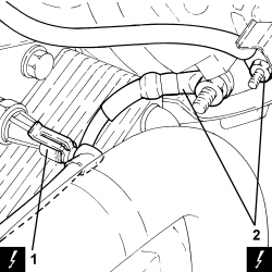
    Op. 1004D40 ENGINE - POSITION ON STAND AND REMOVE1. Disconnect the electrical connection for the air conditioning compressor engagement solenoid.
DescriptionConnector
1Air conditioning compressor engagement solenoidSee L021 AIR CONDITIONING COMPRESSOR ENGAGEMENT SOLENOID VALVE
1. Disconnect the electrical connection for the minimum engine oil pressure switch.
DescriptionConnector
1Insufficient engine oil pressure sensor    See K030 INSUFFICIENT ENGINE OIL PRESSURE SENSOR
2. Undo the fixing nuts and disconnect the electrical connections for the alternator.
DescriptionConnector
2Alternator    See A010 ALARM CENTRAL LOCKING NOT WORKING
1. Disconnect the electrical connection for the rpm sensor.
DescriptionConnector
1Rpm sensor    See K046 RPM SENSOR
2. Disconnect the electrical connection for the engine oil level sensor.
DescriptionConnector
2Engine oil level sensor    See K032 ENGINE OIL LEVEL SENSOR
1. Disconnect the glow plug electrical connections.
DescriptionConnector
1Heater plugs    See A040 HEATER PLUGS
2. Disconnect the electrical connection for the fuel pressure regulator.
DescriptionConnector
2Fuel pressure regulator on rail    See N087 FUEL PRESSURE REGULATOR ON RAIL
1. Disconnect the electrical connections for the injectors.
DescriptionConnector
1Injector    See N070 INJECTOR
2. Disconnect the electrical connection for the E.G.R. solenoid valve.
DescriptionConnector
2EGR solenoid valve    See L030 EGR SOLENOID VALVE
3. Disconnect the electrical connection for the turbo sensor.
DescriptionConnector
3Supercharging sensorSee K082 SUPERCHARGING SENSOR
1. Disconnect the electrical connection for the air temperature sensor.
DescriptionConnector
1Engine coolant temperature sensor/sender unit    See K036 ENGINE COOLANT TEMPERATURE SENSOR/SENDER UNIT
2. Disconnect the electrical connection for the throttle casing.
DescriptionConnector
2Integrated throttle casing actuator    See N075 INTEGRATED THROTTLE CASING ACTUATOR
3. Disconnect the electrical connection for the fuel pressure sensor.
DescriptionConnector
3Fuel pressure sensor    See K083 FUEL PRESSURE SENSOR
- Remove the engine wiring.1. Loosen the bands and remove the heater water supply and return pipes.2. Undo the nut (2a), loosen the bands (2b) and (2c) and remove the duplex pipes (2d).
1. Disconnect the pipes from the vacuum reservoir.2. Undo the bolts and remove the mounting complete with vacuum reservoir.
1. Undo the bolts and remove the protective timing cover.
1. Undo the bolts and remove the timing belt (1b) side guard (1a).2. Undo the bolts (2a), disconnect the hose (2b) and remove the water pump rigid return pipe (2c).3. Undo the bolts (3a) and remove the engine oil dipstick tube (3b).
- Undo the bolts and disconnect the E.G.R. exhaust gas intake hose from the exhaust manifold.1. Undo the turbocharger engine oil supply pipe and disconnect it.2. Undo the bolts and disconnect the engine oil return hose from the turbocharger.3. Undo the nuts (3a) and remove the exhaust manifold - turbocharger assembly complete with precatalyzer (3b).- Remove the gasket.
1. Adjust the moving tensioner (1a) using a spanner to slacken the single engine component drivebelt (1b) tension and remove it.2. Undo the bolts (2a) and remove the crankshaft pulley (2b).3. Undo the bolt (3a) and remove the auxiliary drive belt fixed tensioner (3b).
1. Undo the bolts (1a) and remove the rigid power unit support (1b).
1. Undo the moving tensioner (1a) bolt and remove the timing belt (1b).
1. Undo the pressure pump support side bolts.2. Undo the connectors (2a), (2b) and remove the rigid pipe from the pressure pump to the fuel manifold (2c).
When refitting, use a new rigid pipe between the pump and the fuel manifold.
3. Loosen the bands (3a) and (3b) and remove the pipe from the pressure pump to the fuel return manifold pipe (3c).
1. Undo the front bolt (1a) and remove the pressure pump mounting (1b) complete with alternator (1c).
1. Undo the bolts (1a) and remove the tappet cover (1b) complete with gasket.2. Undo the bolts (2a) and remove the cylinder head assembly (2b).3. Remove the cylinder head gasket.
1. Undo the bolts (1a) and remove the mounting (1b) complete with air conditioning compressor (1c).
- Rotate the engine through 180° on the overhaul stand.1. Undo the bolts fixing the oil sump to the gearbox.2. Unscrew the bolts (2a) securing the sump to the crankcase, timing side and gearbox side, using the tool (2b).
ToolDescriptionFunctionValidity
1860833000SpannerLoosen/tighten the timing side and gearbox side bolts securing the crankcase sump1.9 JTD 8V
3. Undo the side bolts fixing the crankcase sump.4. Remove the sealant using the tool (4a) and remove the engine oil sump (4b).
ToolDescriptionFunctionValidity
1870718000BladeCut the crankcase sump sealant