194000248 - 1016C10 SINGLE CYLINDER HEAD - R.R. AND REPLACE GASKET

| Description | Connector | |
|---|---|---|
| 4 | Exhaust side timing sensor | See K107 EXHAUST SIDE TIMING SENSOR |
| Description | Connector | |
|---|---|---|
| 5 | Inlet side timing sensor | See K106 INTAKE SIDE TIMING SENSOR |
| Description | Connector | |
|---|---|---|
| 6 | Electronic thermostat | See N086 ELECTRONIC THERMOSTAT |
| Description | Connector | |
|---|---|---|
| 7 | Engine coolant temperature sensor/sender unit | See K036 ENGINE COOLANT TEMPERATURE SENSOR/SENDER UNIT |

| Description | Connector | |
|---|---|---|
| 2 | Engine management control unit | See M010 ENGINE MANAGEMENT ECU |
| Description | Connector | |
|---|---|---|
| 3 | Variable geometry solenoid valve | See L015 VARIABLE GEOMETRY SOLENOID VALVE |

| Description | Connector | |
|---|---|---|
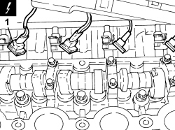
| 1 | Injector | See N070 INJECTOR |
| Description | Connector | |
|---|---|---|
| 1 | Integrated throttle casing actuator | See N075 THROTTLE BODY ACTUATOR |
| Description | Connector | |
|---|---|---|
| 2 | Fuel vapour recovery solenoid valve | See L010 FUEL VAPOUR RECOVERY SOLENOID VALVE |
| Description | Connector | |
|---|---|---|
| 5 | Inlet side phase transformer solenoid valve | See N092 PHASE SHIFTER SOLENOID VALVE ON INTAKE SIDE |

| Description | Connector | |
|---|---|---|
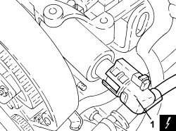
| 1 | Exhaust side phase transformer solenoid valve | See N093 PHASE SHIFTER SOLENOID VALVE ON EXHAUST SIDE |
| Description | Connector | |
|---|---|---|
| 1 | Engine oil pressure sensor (switch) | See K030 LOW ENGINE OIL PRESSURE SENSOR (SWITCH) |
| Description | Connector | |
|---|---|---|
| 2 | Air conditioning compressor engagement electro-magnet | See L020 AIR CONDITIONING COMPRESSOR ENGAGEMENT ELECTRO-MAGNET |

| Description | Connector | |
|---|---|---|
| 1 | Engine coolant temperature sensor/sender unit | See K036 ENGINE COOLANT TEMPERATURE SENSOR/SENDER UNIT |


| The bolts should be undone in the order illustrated in the diagram in two distinct stages: firstly loosen all ten bolts by 90° and then by 180°. |

| Measurement | Value | Validity | ||
|---|---|---|---|---|
| Cylinder head lower surface flatness (mm) | 0.05 | 1.82.2 16V | ||
| Component | Fastening | dia | Value (daNm) | Validity |
|---|---|---|---|---|
| Cylinder head | Bolt (to be replaced) | - | 2.5 + 90° + 90° + 90° + 45° | 1.8 |
