198002771 - INTRODUCTION - STEERING
CONSTRUCTION SPECIFICATIONS
The steering wheel structure is made from magnesium to reduce its weight and improve its strength. Axially and height adjustable steering wheel. The steering column is supported by a steel mounting, in turn secured to a steel bracket.The stiffness of these components contributes significantly to minimising steering wheel vibrations.The steering column is a sliding telescopic structure, in order to improve safety.The steering box is the constant ratio type (51mm/fixed rev) whilst the servocontrol is the electric type located on the steering column.The steering box has a different arm length and travel according to the size of tyre requested:- 148mm rack travel with 15" - 16" - 17" tyres- 140mm rack travel with 18" tyres.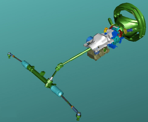
ELECTRIC STEERING
Basic strategies
Depending on the driver''s requirements and the speed of the vehicle, the electric steering control unit controls the electric servomotor which assists the steering column to turn.The motor applies a torque to the steering column by means of a worm screw mechanism, thereby reducing the effort of steering for the driver.Variable servoassistance according to vehicle speed
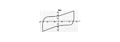
As the vehicle speed increases, the torque that needs to be applied to the steering wheel decreases proportionally; this is because the resistance force at the wheels decreases as the speed increases.Consequently, the control unit, using the speedometer signal, reduces the power-assistance torque.Active return
The active return function refers to the realignment function normally produced by the geometry of the vehicle front section when the steering is released after steering at low speed.This function makes realignment faster and more precise, causing the servo motor to aid the normal geometric effect of the front suspension, which is usually very limited at low speeds.The active return correction varies depending on the speed of the vehicle:
- it is greatest at low speeds
- it is lowest or disabled at high speeds
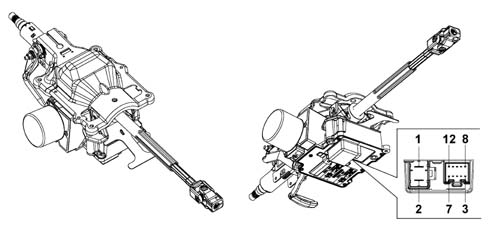
Geared motor
The geared motor unit comprises an aluminium casting secured to the vehicle chassis.The geared motor gear is coaxial and integral with the steering column. This gear is made of steel, whilst the toothed gear connected to the outlet shaft is made of co-moulded plastic.The metal part of the gear is in one piece with the electric motor shaft, which transmits the steering torque to be added (i.e. the servomotor torque to that applied by the driver).The input and output shafts are linked to each other by a torsion bar with calibrated elasticity.When there is resistance torque at the wheels, the input shaft applies torsion to the torsion bar; the input shaft and the output shaft are therefore offset at an angle proportional to the torque applied to the steering wheel.A torque sensor, fitted inside the input shaft, measures the difference of the angle between the input shaft and the output shaft and supplies an electrical signal to the control unit that is proportional to the difference.The geared motor unit casing also houses the external part of the torque and position sensor.Finally the input shaft support sleeve is also secured to the casing; the steering wheel is mounted here and it also houses the ignition switch and steering column switch unit.Electric steering pinout
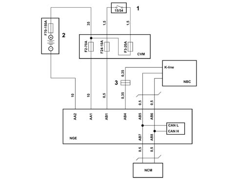
The control unit has two connections:
- one two-way power supply connection,
- one 10-way connection to the CAN and signals.
Operation
The system provides steering assistance via the application of torque generated by a (brush-less) electric motor; it is transmitted to the steering column via a worm screw mechanism - helical toothed gear.A functional diagram of the system is provided below.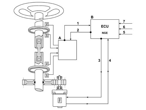
The power-assistance torque to be added to that applied by the driver is determined on the following parameters:
- torque applied by driver,
- vehicle speed,
- angular steering wheel position,
- angular steering wheel speed,
- selected level of assistance (City or Normal).
In all operating conditions the system:
- keeps the force required to steer under a determined value, which depends on the selected level of assistance (City or Normal);
- ensures the correct return to centre of the steering wheel during realignment (active return) at low speeds;
- ensures the dampening of steering wheel oscillation during the return to centre (dampening function).
Control strategies
The power-assistance torque is determined by the following components:
- a main component, dependent on the torque applied by the driver and the level of power-assistance selected (City or Normal);
- two components that carry out Dampening and Active Return, dependent on steering speed (and torque applied by the driver) and steering wheel angle, respectively;
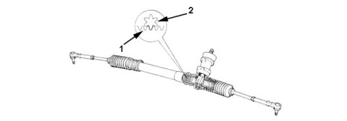
RACK AND PINION STEERING BOX
Specifications
Details (steering box employed with 15" - 16" - 17" tyres)- splitter ratio equal to 51 mm/fixed revolutions- steering wheel angle/wheel angle ratio equal to 16°/1° (referring to rack centre)- steering wheel turns: 2.9 for a rack travel of 148 mm- turning circle between pavements: 10.4 m.Details (steering box employed with 18" tyres)- splitter ratio equal to 51 mm/fixed revolutions- steering wheel angle/wheel angle ratio equal to 16°/1° (referring to rack centre)- steering wheel turns: 2.745 for a rack travel of 140 mm- turning circle between pavements: 11 m.Constant ratio steering box