| STEP | CHECK TO BE PERFORMED | REMEDIAL ACTION IF THE CHECK IS NOT OK |
|---|
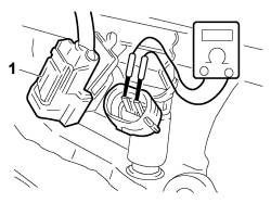
| 1 | Injection signal check- Prepare the diagnostic equipment for a voltage graph assimilation.
- Select the "VOLTMETER" function from the "INSTRUMENT" menu with the time set at 1 second.
- Connect the probes between the pins of the injector that is not working.
- Press the START button on the diagnostic equipment to begin creating a graph.
- Let the engine be driven and check that the signal corresponds to the enclosed graph
| Move on to Step 2 |
| 2 | Injection wiring check- Check the continuity of the wiring for the injection signals between the injectors and the engine control unit
See E5030 PETROL ENGINES ELECTRONIC MANAGEMENT Move on to Step 3 | Restore the correct wiring between the engine control unit and the injectors.Replace the engine management control unit Op. 1056B82 INJECTION/IGNITION SYSTEM E.C.U. (ONE) - R + R |
| 3 | Injector supply check- Check that the injectors are correctly supplied
See E5030 PETROL ENGINES ELECTRONIC MANAGEMENT Move on to Step 4 | Restore the correct supply for the injectors |
| 4 | Injector resistance check- Disconnect the injector connector
- Connect the Examiner in ohmmeter mode between the injector terminals and then check the resistance: the value should be 15 Ohm ±20% at 20°C
| Replace the injector Op. 1056B70 INJECTOR (ONE) - R + R WITH FUEL MANIFOLD PIPE REMOVED - INCLUDES SEAL REPLACEMNT |