| STEP | CHECK TO BE PERFORMED | REMEDIAL ACTION IF THE CHECK IS NOT OK |
|---|
| 1 | Control unit +30 power supply checkSelect the VOLTMETER mode from the INSTRUMENT menuConnect pin 1 to earth of the CPP control unit See E7060 TYRE INFLATION PRESSURE CONTROL SYSTEMCheck that there is a battery voltage of 12 VMove on to Step 2 | Restore the correct continuity for the wiring. |
| 2 | Control unit +15 power supply checkPosition the diagnostic equipment.Select the VOLTMETER mode from the INSTRUMENT menuTurn the key to the MAR positionConnect pin 16 to earthCheck that there is a battery voltage of 12 V See E7060 TYRE INFLATION PRESSURE CONTROL SYSTEM | Restore wiring continuity |
| 3 | Earth checkDisconnect the negative battery terminalDisconnect the CPP control unit connectorWith the diagnostic instrument in ohmmeter modeConnect pin 10 of the wiring-side connector to earthCheck that the resistance is less than 1 Ohm | Restore the right-hand side dashboard area earth. |
| 4 | A-bus serial line checkDisconnect the negative battery terminalDisconnect the CPP control unit connectorDisconnect the Body Computer-side connectorWith the diagnostic instrument in ohmmeter modeConnect pin 18 of the CPP-side connector to pin 10 of the Body Computer-side connectorCheck that the resistance is less than 1 Ohm | Restore the correct connection continuity. |
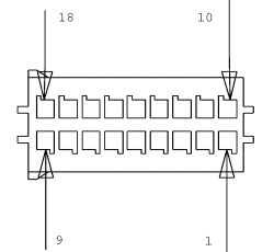
| Pin | Function |
|---|
| 1 | Power supply +30 |
| 2 | L.F. transmitter power supply |
| 3 | Left rear L.F. transmitter signal |
| 4 | Left front L.F. transmitter signal |
| 5 | Right rear L.F. transmitter signal |
| 6 | Right front L.F. transmitter signal |
| 7 | N.C. |
| 8 | B-CAN H network |
| 9 | B-CAN L network |
| 10 | Earth |
| 11 | N.C. |
| 12 | Left-hand rear L.F. transmitter earth |
| 13 | Left-hand front L.F. transmitter earth |
| 14 | Right-hand rear L.F. transmitter earth |
| 15 | Right-hand front L.F. transmitter earth |
| 16 | Control unit ignition operated power supply (+15) |
| 17 | K line |
| 18 | A-bus serial line |