| STEP | CHECK TO BE PERFORMED | REMEDIAL ACTION IF THE CHECK IS NOT OK |
|---|
| 1 | Check the wiring· Check that the connector is correctly inserted in the other part.· Try to move it from its housing by making small movements in all directions, grasping the connector body in your fingers and the wiring in your hand. The connector must stay in place· Exercise a moderate pulling force. The connector must stay in place· check whether the power supply goes off, goes on and/or vice versa (touching/not touching)· Pull the lead and check the stability in the groove (should not move back): exercise repeated pull-push-pull cycles on the lead and ensure its immobility.Examine the crimping:Use a lens to examine the terminal crimping area. The barrels must be turned in a symmetrical way and no strands should poke out of the crimping area.The bare section of cable under the barrels should poke out by about 0.5 | Restore the correct positioning of the connectors |
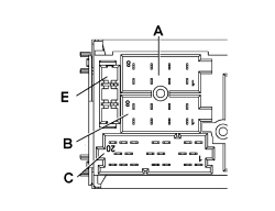
| 2 | Check power supply (+30)· Check for battery voltage +30 across pin 4 of the radio connector A and earth· Check for battery voltage +15 across pin 7 of the radio connector A and earth | Check the continuity of the +30 connection between the Body Computer and the radio See E3510 RADIO Restore +15 power supply See E3510 RADIO |
| 3 | Check power supply (+15)Turn the key to the MAR positionUsing the voltmeter, check for battery voltage +15 across pin 7 of the radio connector A and earth | Restore correct power supply See E3510 RADIO |
| 4 | Earth checkDisconnect the negative battery terminalDisconnect amplifier connector A and connect an ohmmeter across pin 8 and earth and check the resistance is lower than 1 ohm | Restore the earth connection on the tunnel |
| 5 | Amplifier enablement power supply checkTurn the key to the MAR positionUsing the voltmeter, check for a battery voltage across pin 2 of the radio connector C and earth | Restore correct power supply See E3510 RADIO |
| 6 | Amplifier status positive recognition signal checkTurn the key to the MAR position- Using the voltmeter, check for a battery voltage across pin 3 of connector C | Restore correct power supply See E3510 RADIO |
| Pin | Function |
|---|
| A1 | B Can B (high) |
| A2 | Subwoofer amplifier status recognition positive signal for specific acoustic setting. |
| A3 | B Can A (low) |
| A4 | N.C. |
| A5 | Power supply from radio for subwoofer enablement |
| A6 | N.C. |
| A7 | +ignition power supply from F51 |
| A8 | Earth |
| B1 | Right rear speaker + |
| B2 | Right rear speaker - |
| B3 | Right front speaker + |
| B4 | Right front speaker - |
| B5 | Left front speaker + |
| B6 | Left front speaker - |
| B7 | Left rear speaker + |
| B8 | Left rear speaker - |
| C1 | LH AUX signal. |
| C2 | RH AUX signal. |
| C3 | AUX signal |
| C4 | N.C. |
| C5 | N.C. |
| C6 | Power supply from radio for amplifier on aerial (N.C.) |
| D7 | Audio in telephone + (N.C.) |
| D8 | Audio in telephone - (N.C.) |
| D9 | Telephone mute (N.C.) |
| D10 | Steering wheel controls 1 (N.C.) |
| D11 | Steering wheel controls 2 (N.C.) |
| D12 | Earth for external connections (N.C.) |
| E13 | CDC data IN |
| E14 | CDC data OUT |
| E15 | Permanent power supply for CDC |
| E16 | Positive signal for CDC power supply enablement |
| E17 | CDC data GND |
| E18 | CDC audio GND |
| E19 | L input for CDC |
| E20 | R input for CDC |