198002100 - 1080D34 ENGINE OIL VAPOUR SEPARATOR - R + R

Removing ( Refitting )     Op. 1016A10 SOUND-PROOFING COVER - R.R     Op. 1080C24 E.G.R. SYSTEM SOLENOID - R + R 1. Undo the nut (1a) and move the heater plugs control unit (1b) to one side.
1. Loosen the band and disconnect the oil recovery pipe, separator side.
1. Loosen the bands and disconnect the oil vapour intake pipes, separator side.
1. Disconnect the electrical connection for the throttle casing solenoid valve.
DescriptionConnector
-Throttle body solenoid valve    See L062 THROTTLE BODY SOLENOID VALVE
2. Disconnect the vacuum pipes from the vacuum reservoir.
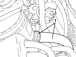
Mark the position of the pipes before removing them.
3. Undo the bolts (3a) and remove the bracket complete with separator and vacuum reservoir (3b).
1. Undo the bolts (1a) and remove the engine oil vapour separator (1b) from the bracket.
Refitting ( Removing ) - Fit the engine oil vapour separator in place and secure it to the bracket using the bolts.- Position the bracket complete with separator and vacuum reservoir in its housing and tighten the bolts to the recommended torque.
ComponentFasteningdia  Value (daNm)Validity
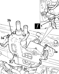
Oil vapour separator bracket - intake chamber sideBoltM60.8 ÷ 1.01.9 JTD 16v
ComponentFasteningdia  Value (daNm)Validity
Oil vapour separator bracket - injection pump mounting sideBoltM82.3 ÷ 2.81.9 JTD 16v
- Connect the vacuum pipes to the vacuum reservoir.- Connect the electrical connection for the throttle casing solenoid valve.- Connect the oil vapour intake pipes, separaator side and tighten the bands.- Connect the oil recovery pipe, separator side and tighten the band.- Place the heater plugs control unit in position and secure it using the nut.    Op. 1080C24 E.G.R. SYSTEM SOLENOID - R + R     Op. 1016A10 SOUND-PROOFING COVER - R.R