198002232 - 5505A35 MAIN BODY COMPUTER/JUNCTION UNIT - R.R.
| Description | Connector | |
|---|---|---|
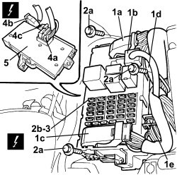
| 1a,1b,1c | JUNCTION UNIT UNDER THE DASHBOARD | See B002 JUNCTION UNIT UNDER DASHBOARD |
| 1d,1e | BODY COMPUTER | See M001 BODY COMPUTER |
| Description | Connector | |
|---|---|---|
| 4b,4c | JUNCTION UNIT UNDER THE DASHBOARD | See B002 JUNCTION UNIT UNDER DASHBOARD |
| 4a | BODY COMPUTER | See M001 BODY COMPUTER |
| If the Body Computer is being replaced, an identical copy of the Body Computer must be obtained from the Parts Dept. as a V.O.R. order, quoting the vehicle chassis number: this copy will contain all the default settings entered when the vehicle was new which are stored in the Parts Dept. database for the vehicle chassis number. |