198002918 - 2110B26 MANUAL GEARBOX (6 SPEED) WITH DIFFERENTIAL - DISMANTLE AND REASSEMBLE, WASH AND CHECK PARTS - REPLACE SYNCHRONIZERS AND INTERNAL PARTS IF NECESSARY

Removing ( Refitting )
The main shaft for the 6 speed version cannot be dismantled.
1. Release the gearbox and differential (1a) from the hydraulic jack (1b) and from the tool (1c) used for removing-refitting it from the vehicle.
ToolDescriptionFunctionValidity
1870644001MountRemoving-refitting gearbox from the vehicle1.9 JTD
1. Fit the gearbox and differential (1a) on the overhaul stand using the tool (1b).
Two mechanics are needed for this operation.
ToolDescriptionFunctionValidity
1871001014MountOverhaul stand mount1.9 JTD
1. Undo the bolts (1a), release the protection (1b) and remove clutch hydraulic actuator (1c) complete with seal.
1. Open the retaining tabs (1a) and remove the oil seal (1b) complete with O-ring from the clutch hydraulic actuator.
1. Remove the left differential internal driveshaft (1a) using tools (1b) and (1c).
ToolDescriptionFunctionValidity
1820229000FlangeDriveshaft removal1.9 JTD 16v
ToolDescriptionFunctionValidity
1821161000Mallet-1.9 JTD 16v
1. Undo the bolts (1a) and remove the flanges on the differential (1b) complete with seals.2. Remove the scraper ring.
1. Undo the bolts (1a) and remove the differential cover (1b).2. Remove the differential.3. Remove the differential bearing outer races.4. Remove the magnet.
1. Undo the reverse shaft bolt.2. Undo the bolts (2a) and remove the gearbox casing (2b).
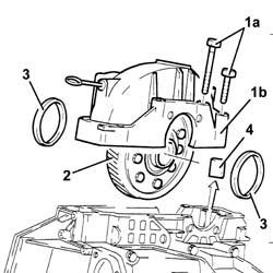
The gearbox casing is sealed to the bellhousing: release the two parts using a wooden or resin hammer.
1. Loosen the bolts (1a) and (1b).2. Release the 5 th speed control rod (2a) from the Reverse fork (2b) and the 5 th speed selector (2c).3. Release the 5th speed fork from the control rod.
1. Simultaneously remove the main shaft, layshaft, reverse shaft and 1st, 2nd, 3rd and 4th speed fork assemblies.
Keep the assemblies joined until they are placed on the workbench.
Separate the forks from the rods.
1. Remove the main shaft rear bearing outer race (1a) using tools (1b) and (1c).
ToolDescriptionFunctionValidity
1870655000Extractor/ Fitting toolBearing race removal1.9 JTD1.4 16v TJet
ToolDescriptionFunctionValidity
1840206001Mallet-1.9 JTD1.4 16v TJet
2. Remove the main shaft scraper ring.3. Remove the lubrication duct.
1. Remove the layshaft rear bearing outer race (1a) using tools (1b) and (1c).
ToolDescriptionFunctionValidity
1870655000Extractor/ Fitting toolBearing race removal1.9 JTD1.4 16v TJet
ToolDescriptionFunctionValidity
1840206001Mallet-1.9 JTD1.4 16v TJet
2. Remove the layshaft scraper ring.
Proceed with dismantling the layshaft following the instructions given below.1. Check that the opening between the gear teeth and the synchronizer ring support planes is >= 0.8 mm.
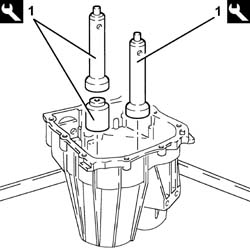
Keep the sliding sleeve raised using a screwdriver.
If the recommended values are not found, the worn synchronizer must be replaced during the reassembly.
1. Remove the rear bearing (1a), the 6 th speed driven gear (1b), using a hydraulic press, the place (1c) and half rings (1d) and a suitable drift (1e).
ToolDescriptionFunctionValidity
1820047002PlateBearing removal1.9 JTD
ToolDescriptionFunctionValidity
1870675000Half-ringsBearing removal1.9 JTD
2. Remove the spacer.
1. Remove the 5th speed driven gear (1a) and the 4th speed driven gear (1b) using a hydraulic press, the plate (1c) and half rings (1d).
ToolDescriptionFunctionValidity
1820047002PlateBearing removal1.9 JTD
ToolDescriptionFunctionValidity
1870675000Half-ringsBearing removal1.9 JTD
2. Remove the spacer.
1. Remove the 3rd speed driven gear (1a) and the 2nd speed driven gear (1b) using a hydraulic press, the plate (1c) and half rings (1d).
ToolDescriptionFunctionValidity
1820047003PlateGear removal1.9 JTD
ToolDescriptionFunctionValidity
1820046000Half-ringsGear removal1.9 JTD
1. Remove the needle bearing for the 2nd speed driven gear.2. Remove the 1 st and 2 nd speed triple cone synchronizer.3. Remove the engagement sliding sleeve for 1 st speed, 2nd speed and reverse (3a) with the mountings (3b).
1. Remove the circlip using suitable pliers.
When refitting, replace the circlip.
1. Remove the hub for the 1st speed, 2nd speed and reverse sliding sleeve (1a), the 1st speed triple cone synchronizer (1b), the 1st speed driven gear (1c), using a hydraulic press, the plate (1d) and the half rings (1e).
ToolDescriptionFunctionValidity
1820047003PlateGear removal1.9 JTD
ToolDescriptionFunctionValidity
1820046000Half-ringsGear removal1.9 JTD
2. Remove the needle bearing for the 1st speed driven gear.
1. Remove the circlip using suitable pliers.
When refitting, replace the circlip.
1. Remove the front bearing (1a) using a hydraulic press, a suitable plate (1b), the reaction base (1c) with the outer race (1d) for the bearing in question inside.
ToolDescriptionFunctionValidity
1870660000Reaction baseBearing removal1.9 JTD
Proceed with dismantling the reverse shaft following the instructions given below.1. Remove the sliding reverse gear assembly.
1. Remove the circlip using suitable pliers.2. Remove the reverse gear synchronizer.3. Remove the spring (3a) from the sliding reverse gear (3b).
1. Remove the pin.2. Remove the needle bearing for the sliding reverse gear (2a) complete with bush (2b).3. Remove the fixed reverse gear.4. Remove the needle bearing for the fixed reverse gear.
Refitting ( Removing ) Proceed with reassembling the reverse shaft following the instructions given below.1. Fit the needle bearing for the sliding reverse gear (1a) on the reverse shaft (1b).2. Fit the fixed reverse gear.3. Fit the needle bearing for the sliding reverse gear complete with bush.4. Fit the pin.
Fitting sliding reverse gear1. Fit the spring (1a) on the sliding reverse gear (1b).2. Fit the reverse gear synchronizer.3. Fit the circlip.
1. Check the position of the synchronizer-spring assembly in relation to the sliding reverse gear as illustrated.
Fit the sliding reverse gear - reverse synchronizer assembly on the reverse shaft. Proceed with reassembling the layshaft following the instructions given below.
Lubricate the bearings with the recommended oil before refitting them.
1. Fit the front bearing (1a) using a hydraulic press, a suitable plate (1b) and the fitting tool (1c).
ToolDescriptionFunctionValidity
1870658000Extractor/ Fitting toolFitting bearings1.9 JTD1.4 16v TJet
1. Using a feeler gauge, measure the housing for the front bearing circlip to be fitted.
1. Fit a new front bearing circlip.
The size of the circlip is selected from those available as spares (1.975; 2.020; 2.065) depending on the previous measurement of the housing.
2. Fit the needle bearing for the 1st speed driven gear.3. Fit the 1st speed driven gear.4. Fit the 1st speed triple cone synchronizer.
1. Fit the hub for the 1st speed, 2nd speed and reverse sliding sleeve (1a) using a hydraulic press, a suitable plate (1b) and the fitting tool (1c).
ToolDescriptionFunctionValidity
1870658000Extractor/ Fitting toolFitting bearings1.9 JTD1.4 16v TJet
1. Fit a new circlip.2. Place the mountings for the 1st, 2nd speed and reverse sliding sleeve in their housings on the hub.3. Fit the 1st speed, 2nd speed and reverse sliding sleeve so that the internal references are aligned with the mountings.
1. Fit the needle bearing for the 2nd speed driven gear.
1. Fit the triple cone synchronizer (1a) on the 2nd speed driven gear (1b).2. Fit the assembly constructed as described in the previous stage on the layshaft.
1. Fit the 3rd speed driven gear (1a) using a hydraulic press, a suitable plate (1b) and the fitting tool (1c).
ToolDescriptionFunctionValidity
1870658000Extractor/ Fitting toolFitting bearings1.9 JTD1.4 16v TJet
1. Fit the spacer.Heat the 4th speed driven gear to 120 °C.2. Fit the 4th speed driven gear (2a) using a hydraulic press, a suitable plate (2b) and the top part of the tool (2c).
ToolDescriptionFunctionValidity
1870658000Extractor/ Fitting toolFitting bearings1.9 JTD1.4 16v TJet
1. Fit the 5th speed driven gear (1a) using a hydraulic press, a suitable plate (1b) and the top part of the tool (1c).
ToolDescriptionFunctionValidity
1870658000Extractor/ Fitting toolFitting bearings1.9 JTD1.4 16v TJet
1. Fit the 6th speed driven gear (1a) using a hydraulic press, a suitable plate (1b) and the top part of the tool (1c).
ToolDescriptionFunctionValidity
1870658000Extractor/ Fitting toolFitting bearings1.9 JTD1.4 16v TJet
1. Fit the rear bearing (1a) using a hydraulic press, a suitable plate (1b) and the fitting tool (1c).
ToolDescriptionFunctionValidity
1870659000Fitting toolFitting bearings1.9 JTD
Fit the main and layshafts simultaneously in their housings.If the following components are being replaced:main shaft,bellhousing support,gearbox casing,main shaft front bearing,main shaft rear bearing,layshaft assembly,layshaft rear bearing,3rd, 4th 5th and 6th speed driven gears,proceed with determining the thickness of the scraper rings and the shims for the main and layshaft bearing pre-loading following the instructions given below.Thoroughly clean the bearing and gearbox casing support surfaces.1. Position the two gauges in the rear bearing seats in the gearbox casing.
ToolDescriptionFunctionValidity
1870648000GaugesPreloading bearings1.9 JTD
1. Fit the reference crossmember on the gearbox casing.
ToolDescriptionFunctionValidity
1870649000Reference crossmemberPreloading bearings1.9 JTD
1. Place the two cylinders for the gauges in contact (without force) with the lower surface of the reference crossmember using a screwdriver and working via the two special openings.2. Lock the two cylinders using the bolts.
Remove the reference crossmember and the gauges from the gearbox casing.1. Fit the two gauges (1a) on the tool plate (1b).
ToolDescriptionFunctionValidity
1870648000GaugesPreloading bearings1.9 JTD
ToolDescriptionFunctionValidity
1870647000MountPreloading bearings1.9 JTD
1. Fit the tool for checking the bearing pre-loading (1a) with the bolts (1b), the spacer (1c), and the disc (1d) specially designed for 6 speed gearboxes.
ToolDescriptionFunctionValidity
1870647000MountPreloading bearings1.9 JTD
1. Match the support for determining the bearing pre-loading kitted out in this way with the base plate complete with gauges.2. Connect the tool to a compressed air line and supply it with a pressure of 0.5 bar so that the two actuators are in contact with the gauges.3. Fit two dial gauges on the tool and zero them with a pre-loading of 3 mm (see reference X in the example for calculating the scraper shims).
Remove the support for determining the bearing pre-loading from the base plate complete with gauges.1. Remove the disc.
1. Position the support for determining the bearing pre-loading on the gearbox casing support and secure it.2. Connect the equipment to an air line and supply it at a pressure of 4 bar.3. Rotate the main and layshafts through ten revolutions using the tool (3a) and a suitable crank (3b).
ToolDescriptionFunctionValidity
1870652000BushPreloading bearings1.9 JTD
Measure the movements in relation to the layshaft and the main shaft using the dial gauges (see reference Y in the example for calculating the scraper shims).Add 0.15 mm to the difference between X and Y for the layshaft to obtain the necessary distance for selecting the size of the scraper ring to be used.Subtract 0.15 mm from the difference between X and Y for the main shaft to obtain the necessary distance for selecting the size of the scraper ring to be used.
Below is an example for calculating the size of scraper shims
Reference distance X (casing)Zero with dial gauge with a pre-loading of 3 mm on the test equipment.
Reference distance Y (shafts)To simplify the situation, let us assume that the difference measured was 0.9 mm for both the layshaft and the main shaft.
Calculation of layshaft scraper shim- 0.15 mm must be added to the difference measured between X and Y; to understand this more easily, immagine that the pointer has to move to the test distance of 0.15 mm, i.e.: 0.9 + 0.15 = 1.05 mm (scraper shim).
Calculation of main shaft scraper shim0.15 mm must be subtracted from the difference measured between X and Y; to understand this more easily, immagine that the pointer has to move to the test distance of 0.15 mm, i.e.: 0.9 - 0.15 = 0.75 mm (scraper ring).
Remove the tool for determining the bearing pre-loading from the gearbox casing support.1. Fit the lubrication duct.2. Fit the main shaft scraper ring of the size calculated.3. Fit the main shaft rear bearing outer race (3a) using a hydraulic press, a suitable plate (3b) and the fitting tool (3c).
ToolDescriptionFunctionValidity
1870657000Fitting toolFitting bearings/bushes1.9 JTD
1. Fit the layshaft scraper ring of the size calculated.2. Fit the main shaft rear bearing outer race (2a) using a hydraulic press, a suitable plate (2b) and the fitting tool (2c).
ToolDescriptionFunctionValidity
1870657000Fitting toolFitting bearings/bushes1.9 JTD
Place the reverse shaft and the 1st, 2nd, 3rd and 4th speed forks and control rods in position.1. Lift up the reverse driven gear and check that the reverse shaft pin is correctly positioned.
1. Fit the 5th speed and reverse control forks.2. Fit the 5 th speed and reverse control rod (2a) and secure it tightening the bolt (2b) to the recommended torque.
ComponentFasteningdia  Value (daNm)Validity
5th speed control rodBoltM82.1 ÷ 2.61.9 JTD
3. Fit the 5 th speed control fork (3a) and secure it tightening the bolt (3b) to the recommended torque.
ComponentFasteningdia  Value (daNm)Validity
5th speed control forkBoltM82.1 ÷ 2.61.9 JTD
Apply sealant to the entire surface matched with the gearbox casing.1. Fit the gearbox casing (1a) and secure it tightening the bolts (1b) to the recommended torque.
ComponentFasteningdia  Value (daNm)Validity
Manual gearbox/differential components casingBoltM92.9 ÷ 3.61.9 JTD
2. Tighten the reverse shaft bolt to the recommended torque.
ComponentFasteningdia  Value (daNm)Validity
Reverse shaftBoltM104.3 ÷ 5.31.9 JTD
Fit the magnet.Fit the differential in its housing complete with bearing outer races.Apply sealant to the entire surface matched with the differential internal housing support.1. Fit the differential internal housing support (1a) and fastening it by tightening the bolts (1b) to the recommended torque.
ComponentFasteningdia  Value (daNm)Validity
Manual gearbox casing differential supportBoltM104.3 ÷ 5.31.9 JTD
ComponentFasteningdia  Value (daNm)Validity
Manual gearbox casing differential supportBoltM82.1 ÷ 2.61.9 JTD
1. Position the flange in its housing on the gearbox side differential (1a) complete with a new seal and secure it tightening the bolts (1b) to the recommended torque.
ComponentFasteningdia  Value (daNm)Validity
Flanges on differentialBoltM82.1 ÷ 2.61.9 JTD
Using a suitable drift, move the pinion side tapered bearing outer race nearer.1. Position the tool complete with dial gauge on the surface of the engine side differential and zero the dial guage with a pre-loading of 1 mm.
ToolDescriptionFunctionValidity
1820085000Dial gauge mountDetermining thickness of thrust ring1.9 JTD 16v
1. Position the tool (1a), complete with dial gauge, on the engine side differential flange (1b) and measure the difference.
ToolDescriptionFunctionValidity
1820085000Dial gauge mountDetermining thickness of thrust ring1.9 JTD 16v
Calculate the size "S" of the scraper ring for the differential bearing pre-loading by adding 0.12 mm to the difference measured.
0.12 corresponds to the recommended interference for the bedding in and pre-loading of the differential bearings.
1. Place the scraper ring or rings of exactly the size or the next largest size to that calculated for the differential bearing pre-loading in the housing.2. Position the flange in its housing on the engine side differential (2a) complete with a new seal and secure it tightening the bolts (2b) to the recommended torque.
ComponentFasteningdia  Value (daNm)Validity
Flanges on differentialBoltM82.1 ÷ 2.61.9 JTD
The matching surfaces of the main shaft cover and the thrust bearing should be lubricated with Molycote PG 21 grease.
- Fit a new oil seal complete with O-ring on the clutch hydraulic actuator and fold the retaining tabs.- Place the hydraulic clutch actuator in position complete with protection and tighten the bolts to the recommended torque.
ComponentFasteningdia  Value (daNm)Validity
Hydraulic clutch actuatorBoltM60.7 ÷ 0.91.9 JTD
Fit the clutch engagement thrust bearing control fork pin.
The two fork pin levers should be lubricated with Molycote PG 21 grease.
Fit the outer non-slip bush.
The self-lubricating Permaglid bushes should not, under any circumstances be lubricated with oil or else the lubricant grease will, in time, mix with the abrasive material of the bush and create an impasto that will accelerate the wear of the actual bush.
Fit the left inner driveshaft.Undo the fastenings and remove the gearbox and differential from the tool.
Two mechanics are needed for this operation.
ToolDescriptionFunctionValidity
1871001014MountOverhaul stand mount1.9 JTD
Remove the support tool from the overhaul stand and put it down.Position the gearbox and differential on the tool used for the removing-refitting from the vehicle.
ToolDescriptionFunctionValidity
1870644001MountRemoving-refitting gearbox from the vehicle1.9 JTD