199000618 - 5560 ON-BOARD INSTRUMENTS
INSTRUMENT PANEL
Indicators
The control panel is installed behind the steering wheel. It is connected to the CAN network and includes 4 gauges built using step motors.
Warning lights
There are also numerous LED negative contrast warning lights (there is also preparation for warning lights that can be activated by the CAN).Buzzer
The instrument panel contains a buzzer with 8 different settings to carry out the following functions:- alarm/warning/danger signals- parking sensor signals (where fitted)- robotized gearbox signals (where present)- Sealt Belt Reminder- direction indicators / hazard warning lights activation- button pressing roger beepThe acoustic signals can vary in intensity and frequency depending on the function signalled.The volume for the alarm signals can be adjusted down to zero (signal excluded) except for the seat belt reminder and direction indicator/hazard warning light signals which is fixed and the parking sensor which has a minimum volume that is not zero.Keys
The instrument is connected with 5 external keys on the left side of the dashboard for the management of the headlamp alignment corrector (buttons CAF+, CAF-), the dimming and the setup menu ("MENU ESC", "+", "-" buttons).

Display
The control panel display is available in three versions depending on the vehicle''s on-board features:- COMFORT type display- MODAL type display- MATRIX type displayDisplays at the Key OFFWith the front doors closed at the key off, the display is not lit up.The display comes on for 10 seconds and shows the clock and the total milometer at the Key OFF when at least one front door is opened/closed.Comfort type displayExample: standard page at Key ON with dipped headlamps on.


Warning lights
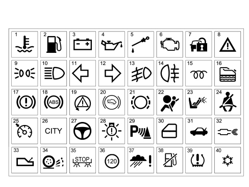
| The "General Failure" warning light summarizes the following signals:- Inertia switch operated- Engine oil pressure sensor failureOn the Comfort and Matrix panel the warning light also summarizes other signals which have a dedicated associated message. |
Connector pin out
The instrument panel (18-way) connector is illustrated.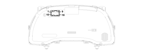
| PIN | FUNCTION |
|---|---|
| 1 | Earth |
| 2 | +30 |
| 3 | +15 (+key) |
| 4 | Not connected |
| 5 | B-CAN A |
| 6 | B-CAN B |
| 7 | Reference signal for headlamp alignment actuators |
| 8 | + dipped headlamps signal for headlamp alignment corrector |
| 9 | Signal from Trip Computer button on steering column switch unit |
| 10 | Not connected |
| 11 | Not connected |
| 12 | Not connected |
| 13 | Signal from controls in panel: “MENU ESC” / “+” |
| 14 | Signal from controls in panel: "headlamp alignment corrector up", "headlamp alignment corrector down" |
| 15 | Operation of buzzer from robotized gearbox (N.C.) |
| 16 | Signal from controls in panel: “–“ |
| 17 | Not connected |
| 18 | Operation of i.e./EOBD failure warning light |
Indicators
SpeedometerThe instrument panel increases the actual speed value slightly (6% + 1 km/h but this increase also depends on the tyres fitted on the vehicle) for safety reasons and never exceeds the maximum tolerance recommended in the directives of the countries where the vehicle is sold.The increase is calculated according to the panel.At the Key ON the indicator is at 0 (zero) km/h (or mph) and the instrument panel then displays the vehicle speed information.Rev counterAt the Key ON the indicator is at 0 (zero) RPM and the instrument panel then displays the engine rpm information.There is also a logic to prevent fluctuations of the rev counter with the engine idling.Fuel level gauge2 seconds after the Key ON the indicator shows the fuel level information.The reading at the start of the "fuel reserve" is red and the warning light is produced by the amber LED in the indicator graphics. The calibration of the gauge ensures maximum precision at the start of the red sector.Engine coolant temperature gauge2 seconds after the Key ON the indicator shows the engine coolant temperature information.The reading at the start of the "danger zone" is red and the warning light is produced by the red LED in the indicator graphics. The calibration of the gauge ensures maximum precision at the start of the red sector.Behaviour of the indicator:- If the temperature is below 50°C the indicator is at the first reference on the scale.- For temperatures of between 50 and 80°C the indicator moves in a linear fashion.- For temperatures between 80 - 115°C (normal operation), the pointer should remain in a stable position in the centre of the scale.- For temperatures between 115 and 124°C (uphill) and between 120 and 115°C (downhill) the pointer should move in a linear fashion.- For temperatures of 124°C (uphill) the pointer remains at the start of the red danger zone on the scale.- For temperatures above 124°C the coolant overheating warning light lights up and, at the same time, the pointer is positioned at the end of the scale.Main functions
The main features are summarized in the table below.| CONTENT | MODAL PANEL | COMFORT PANEL | MATRIX PANEL |
|---|---|---|---|
| Speedometer | X | X | X |
| Rev counter | X | X | X |
| Fuel level gauge | X | X | X |
| Engine coolant temperature gauge | X | X | X |
| Engine coolant temperature gauge | - | - | X |
| Engine coolant pressure gauge | X | X | X |
| Headlamp alignment corrector | X | X | X |
| Milometer | X | X | X |
| Outside temperature and ice danger | - | X | X |
| Dimmer light | X | X | X |
| Reduced set up menu | X | - | - |
| Complete set up menu | - | X | X |
| Time | X | - | - |
| Time and Date | - | X | X |
| Trip Computer | X | X | X |
| Service (planned maintenance) | - | X | X |
| Repetition of audio information | - | X | X |
| Display of hands-free functions (Bluetooth) | - | X | X |
| Navigation information display | - | - | X |
| Acquisition of data from vehicle | - | X | X |
| Telediagnosis | - | X | X |
| Logistic Mode | X | X | X |
| Buzzer | X | X | X |
| Particle filter + deteriorated oil | - | X | X |
| Alternator failure | X | X | X |
| Minimum engine oil pressure | X | X | X |
| Minimum oil level |
| ... DATA ERROR - CROPPED TEXT | Ошибка данных - Текст обрезан ... |
|---|