199000616 - 5550 WARNING AND MANOEUVRE SIGNALS

STEERING COLUMN SWITCH UNIT MODULE

The steering column switch unit module includes the exterior lighting controls (on the lights lever on the left) and the windscreen/rearscreen washing and wiping controls (on the wiper lever on the right).The module also houses the Trip function button (right side) and the Cruise Control lever (optional).

Introduction

The steering column switch unit basically groups the following functions together:- Controls for exterior lights and direction indicators- Controls for windscreen washing and wiping functions- TRIP function button- Controls for Cruise Control

Operation

Left lever
A - Lights selectorB - Lights flasher - main beam headlamps switchC - Direction indicatorsLight selectorThe selector is a ring nut with 3 stable positions located at the end of the lever and activated by turning it along the axis of the lever.- Pos. 1 = No circuit operated- Pos. 2 = Side lights- Pos. 3 = Dipped headlampsFlasher - main beam headlamps switchThe "light flasher" control is operated by pulling the stalk from rest position towards the steering wheel; the operation is unstable i.e. the stalk returns to the rest position when released.The "fixed main beam headlamps" command is produced by pulling the lever in the same way as for the flasher but making it complete a greater travel, as far as the second position ("main beam headlamps" contact).To switch the main beam headlamps off, the lever must be pulled to the main beam position in the same way as for switching them on.Direction indicators controlThe command is produced by moving the lever on the steering wheel plane in both directions, upwards for the right direction indicators and downwards for the left ones.The lever has two distinct activating modes: one unstable one known as "changing lane" and one stable one known as "changing direction".The unstable activation on the release of the lever reopens the electrical contact that has closed.The stable activation has an automatic release device that returns the lever to the rest position when the manoeuvre is completed (rotation of the steering wheel in the same direction as the lever).Right lever
A - Windscreen wiperB - Windscreen wiper intermittent operation / rain sensor setting (if present) ring nutC - Windscreen washerD - Rearscreen wiperE - Rearscreen washerF - TRIP buttonWindscreen wiper controlThe windscreen wiper is operated by moving the lever along the plane of the steering wheel. There are 5 different activation positions, from the bottom, in this order:- Antipanic (unstable)- OFF- Intermittent / Automatic- Continuous 1st speed- Continuous 2nd speedWindscreen wiper intermittent selector (rain sensor sensitivity)The adjustment takes place by turning the ring nut into 4 stable positions.4 different pause times for the intermittent operation of the windscreen wiper correspond to these positions.If a rain sensor is fitted, the positions correspond to the 4 rain sensor settings.- MAX pause (MIN setting)- Medium - high pause (setting 2)- Medium - low pause (setting 3)- MIN pause (MAX setting)Windscreen washer controlThe control for activating the two-way pump for washing the front windscreen is produced by pulling the lever towards the steering wheel crown; the activation is unstable.Rearscreen wiper controlThe rearscreen wiper is controlled by rotating a ring nut in 2 stable positions halfway along the lever.Rearscreen washer controlThe control for activating the two-way pump for washing the rearscreen is produced by pulling the lever towards the dashboard; the activation is unstable.TRIP buttonBy pressing the unstable TRIP button on the lever the relevant commands are sent to the instrument panel.Cruise control lever    See descriptions 5580A CRUISE CONTROL SYSTEM

Electrical connections

The steering column switch unit is connected to the vehicle wiring by means of a single connector.All the signals sent are the digital type so that multiple information is sent through a single connection.
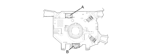
connector A steering column switch unitconnector B clock springConnector a steering column switch unit pin out
PinDescription
1Direction indicators command to Body Computer
2Flasher command to Body Computer
3Side lights/dipped headlamps command to Body Computer
4Rearscreen wiper signals to Body Computer
5Windscreen/rearscreen washer signals to Body Computer
6A-bus serial line (signal from rain sensor to Body Computer)
7Windscreen wiper signals (low/high speed, cam, intermittent/auto operation) to Body Computer
8Cruise control signal (on, +/-, resume) to Body Computer
9Trip command signal to the instrument panel
10Power earth
11N.C.
12N.C.
Clock spring: connector bThe clock spring transfers the electrical signal to controls on the steering wheel (horn and other optional controls) and connects the airbag module without risk of breakage.For more details, see    See descriptions 5580C AIR BAG SYSTEM