199000406 - 1004E20 ENGINE - DISMANTLE AND REASSEMBLE FOLLOWING OPERATION 1004E10 - WASH AND CHECK DISMANTLED PARTS - REFIT CYLINDER HEAD AND OIL SUMP - DOES NOT INCLUDE REPAIRS TO CYLINDER HEAD AND AUXILIARY UNIT
| Tool | Description | Function | Validity |
|---|---|---|---|
| 1860815000 | Flange | Crankshaft rotation | 1.9 Multijet |
| Tool | Description | Function | Validity |
|---|---|---|---|
| 1860815000 | Flange | Crankshaft rotation | 1.9 Multijet |
| Measurement | Value | Validity |
|---|---|---|
| Crankshaft endfloat (mm) | 0.049 ÷ 0.211 | 1.9 Multijet |
| Measurement | Value | Validity |
|---|---|---|
| Cylinder head support surface flatness (mm) | < 0.1 | 1.2 8v1.4 8v1.4 16v1.9 Multijet |
| Measurement | Value | Validity |
|---|---|---|
| Cylinder liner diameter - Grade A (mm) | 82.000 ÷ 82.010 | 1.9 Multijet |
| Measurement | Value | Validity |
|---|---|---|
| Cylinder liner diameter - Grade B (mm) | 82.010 ÷ 82.020 | 1.9 Multijet |
| Measurement | Value | Validity |
|---|---|---|
| Cylinder liner diameter - Grade C (mm) | 82.020 ÷ 82.030 | 1.9 Multijet |
| Measurement | Value | Validity |
|---|---|---|
| Cylinder liner taper (mm) | < 0.005 | 1.9 Multijet |
| Measurement | Value | Validity |
|---|---|---|
| Cylinder liner ovality (mm) | < 0.05 | 1.9 Multijet |
| In the case of reaming, all the bores must have the same oversize. |
| Measurement | Value | Validity |
|---|---|---|
| Cylinder liner diameter oversize (mm) | 0.1 | 1.2 8v1.4 8v1.4 16v1.3 Multijet1.9 Multijet |

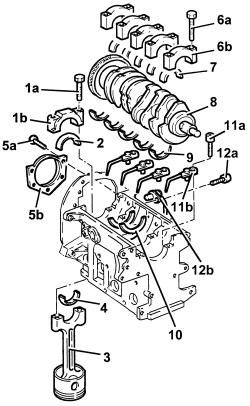
| The bearing caps have progressively numbered references (from zero to four starting from the front of the engine) which define the fitting position. |

| Component | Fastening | dia | Value (daNm) | Validity |
|---|---|---|---|---|
| Main bearing caps | Bolt | M12 | 2.4 ÷ 2.6 + 100° | 1.9 Multijet |
| Tool | Description | Function | Validity |
|---|---|---|---|
| 1860942000 | Torque wrench | Tighten bolts to torque plus angle |
| Measurement | Value | Validity |
|---|---|---|
| Main journal seat diameter (mm) | 63.705 ÷ 63.718 | 1.9 Multijet |
| Measurement | Value | Validity |
|---|---|---|
| Main journal diameter - Category A (mm) | 59.994 ÷ 60.000 | 1.9 Multijet |
| Measurement | Value | Validity |
|---|---|---|
| Main journal diameter - Category B (mm) | 59.987 ÷ 59.993 | 1.9 Multijet |
| Measurement | Value | Validity |
|---|---|---|
| Main journal diameter - Category C (mm) | 59.982 ÷ 59.986 | 1.9 Multijet |
| Measurement | Value | Validity |
|---|---|---|
| Main journal diameter oversize (mm) | 0.127 | 1.9 Multijet |
| Crankpin undersizes higher than the value mentioned will adversely affect the structural resistance of the crankshaft (following contact between the tool and rolled connectors). As far as the above is concerned, if the regrinding requires undersizes greater than 0.127 mm, then the crankshaft must be replaced and a new one ordered from the Parts Dept. The half-bearings used for undersizes of more than 0.127 mm should not be ordered from the Parts Dept. (even if the number is still quoted). |
| Measurement | Value | Validity |
|---|---|---|
| Crankpin diameter - Category A (mm) | 50.799 ÷ 50.805 | 1.9 Multijet |
| Measurement | Value | Validity |
|---|---|---|
| Crankpin diameter - Category B (mm) | 50.793 ÷ 50.799 | 1.9 Multijet |
| Measurement | Value | Validity |
|---|---|---|
| Crankpin diameter - Category C (mm) | 50.787 ÷ 50.793 | 1.9 Multijet |
| Measurement | Value | Validity |
|---|---|---|
| Crankpin diameter undersize (mm) | 0.127 | 1.2 8v1.4 8v1.4 16v1.3 Multijet1.9 Multijet |
| Crankpin undersizes higher than the value mentioned will adversely affect the structural resistance of the crankshaft (following contact between the tool and rolled connectors). As far as the above is concerned, if the regrinding requires undersizes greater than 0.127 mm, then the crankshaft must be replaced and a new one ordered from the Parts Dept. The half-bearings used for undersizes of more than 0.127 mm should not be ordered from the Parts Dept. (even if the number is still quoted). |
| If the crankshaft has been ground, fit new oversize half-bearings to restore the initial tolerance conditions. |
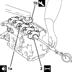
| Check one journal at a time, without rotating the crankshaft. |

| The bearing caps have progressively numbered references (from zero to four starting from the front of the engine) which define the fitting position. |

| Component | Fastening | dia | Value (daNm) | Validity |
|---|---|---|---|---|
| Main bearing caps | Bolt | M12 | 2.4 ÷ 2.6 + 100° | 1.9 Multijet |
| Tool | Description | Function | Validity |
|---|---|---|---|
| 1860942000 | Torque wrench | Tighten bolts to torque plus angle |

| Measurement | Value | Validity |
|---|---|---|
| Clearance between main bearings - crankshaft main journals (mm) | 0.011 ÷ 0.071 | 1.9 Multijet |
| If the figure measured is outside of the tolerance, replace the half-bearings with ones of the correct size and category. |

| Measurement | Value | Validity |
|---|---|---|
| Small end bush inner diameter (mm) | 26.006 ÷ 26.012 | 1.9 Multijet |
| Measurement | Value | Validity |
|---|---|---|
| Piston pin housing diameter in pistons (mm) | 25.999 ÷ 26.004 | 1.9 Multijet |
| Measurement | Value | Validity |
|---|---|---|
| Piston pin outer diameter (mm) | 25.982 ÷ 25.987 | 1.9 Multijet |
| Measurement | Value | Validity |
|---|---|---|
| Cylinder compression 1st sealing ring gap (mm) | 0.20 ÷ 0.35 | 1.9 Multijet |
| Measurement | Value | Validity |
|---|---|---|
| Cylinder compression 2nd sealing ring gap (mm) | 0.25 ÷ 0.50 | 1.9 Multijet |
| Measurement | Value | Validity |
|---|---|---|
| Piston oil scraper ring gap (mm) | 0.25 ÷ 0.50 | 1.3 Multijet1.9 Multijet |
| Measurement | Value | Validity |
|---|---|---|
| Sealing ring seat in piston - 1st groove (mm) | 2.080 ÷ 2.100 | 1.9 Multijet |
| Measurement | Value | Validity |
|---|---|---|
| Sealing ring seat in piston - 2nd groove (mm) | 2.020 ÷ 2.040 | 1.9 Multijet |
| Measurement | Value | Validity |
|---|---|---|
| Sealing ring seat in piston - 3rd groove (mm) | 2.020 ÷ 2.040 | 1.9 Multijet |
| Measurement | Value | Validity |
|---|---|---|
| Cylinder compression 1st sealing ring thickness (mm) | 1.970 ÷ 1.995 | 1.3 Multijet1.9 Multijet |
| Measurement | Value | Validity |
|---|---|---|
| Cylinder compression 2nd sealing ring thickness (mm) | 1.970 ÷ 1.995 | 1.9 Multijet |
| Measurement | Value | Validity |
|---|---|---|
| Piston oil scraper ring size (mm) | 1.970 ÷ 1.990 | 1.3 Multijet1.9 Multijet |
| Measurement | Value | Validity |
|---|---|---|
| Piston outer diameter -Grade A (mm) | 81.920 ÷ 81.930 | 1.9 Multijet |
| Measurement | Value | Validity |
|---|---|---|
| Piston outer diameter - Grade B (mm) | 81.930 ÷ 81.940 | 1.9 Multijet |
| Measurement | Value | Validity |
|---|---|---|
| Piston outer diameter - Grade C (mm) | 81.940 ÷ 81.950 | 1.9 Multijet |
| Measure perpendicular to the gudgeon pin axis, 8 mm from the lower edge of the skirt. |
| Measurement | Value | Validity |
|---|---|---|
| Cylinder compression 1st sealing ring endfloat (mm) | 0.0085 ÷ 0.130 | 1.9 Multijet |
| Measurement | Value | Validity |
|---|---|---|
| Cylinder compression 2nd sealing ring endfloat (mm) | 0.025 ÷ 0.070 | 1.9 Multijet |
| Measurement | Value | Validity |
|---|---|---|
| Oil scraper ring endfloat (mm) | 0.030 ÷ 0.070 | 1.3 Multijet1.9 Multijet |
| Component | Fastening | dia | Value (daNm) | Validity |
|---|---|---|---|---|
| Connecting rod caps | Bolt | M9 | 2.4 ÷ 2.6 + 60° | 1.9 Multijet |
| Tool | Description | Function | Validity |
|---|---|---|---|
| 1860942000 | Torque wrench | Tighten bolts to torque plus angle |
| Measurement | Value | Validity |
|---|---|---|
| Big end diameter (mm) | 53.897 ÷ 53.909 | 1.9 Multijet |
| The crankshaft supplied by the Parts Dept. comes without half-bearings and the main journals and crankpins are the "normal" size; the half-bearings to be fitted must therefore be selected identifying the class of each main journal and crankpin for the new crankshaft. |

| Only use the codes that relate to the key, all other codes on the flywheel should not be used. |
| The bearing caps have progressively numbered references (from zero to four starting from the front of the engine) which define the fitting position. |

| Component | Fastening | dia | Value (daNm) | Validity |
|---|---|---|---|---|
| Main bearing caps | Bolt | M12 | 2.4 ÷ 2.6 + 100° | 1.9 Multijet |
| Tool | Description | Function | Validity |
|---|---|---|---|
| 1860942000 | Torque wrench | Tighten bolts to torque plus angle |
| Tool | Description | Function | Validity |
|---|---|---|---|
| 1860815000 | Flange | Crankshaft rotation | 1.9 Multijet |
| For the selection of the connecting rod half-bearings, follow the procedure described previously for the main journal half-bearings. |
| The piston-connecting rod assemblies are fitted in the cylinder block/crankcase so that the combustion chamber in the piston is facing the intake side. |
| Fit the connecting rods so that the number stamped on each rod faces toward the same side as the number stamped on the big end (inlet side). |
| Component | Fastening | dia | Value (daNm) | Validity |
|---|---|---|---|---|
| Connecting rod caps | Bolt | M9 | 2.4 ÷ 2.6 + 60° | 1.9 Multijet |
| Tool | Description | Function | Validity |
|---|---|---|---|
| 1860942000 | Torque wrench | Tighten bolts to torque plus angle |

| Measurement | Value | Validity |
|---|---|---|
| Crankpin half-bearings - Category A (red) (mm) | 1.527 ÷ 1.531 | 1.9 Multijet |
| Measurement | Value | Validity |
|---|---|---|
| Crankpin half-bearings - Category B (light blue) (mm) | 1.530 ÷ 1.534 | 1.9 Multijet |
| Measurement | Value | Validity |
|---|---|---|
| Crankpin half-bearings - Category C (yellow) (mm) | 1.533 ÷ 1.537 | 1.9 Multijet |
| Measurement | Value | Validity |
|---|---|---|
| Clearance between connecting rod bearings - crankpin bearings (mm) | 0.030 ÷ 0.056 | 1.9 Multijet |
| Fit the connecting rods so that the number stamped on each rod faces toward the same side as the number stamped on the big end (inlet side). |
| Component | Fastening | dia | Value (daNm) | Validity |
|---|---|---|---|---|
| Connecting rod caps | Bolt | M9 | 2.4 ÷ 2.6 + 60° | 1.9 Multijet |
| Tool | Description | Function | Validity |
|---|---|---|---|
| 1860942000 | Torque wrench | Tighten bolts to torque plus angle |
| Tool | Description | Function | Validity |
|---|---|---|---|
| 1860815000 | Flange | Crankshaft rotation | 1.9 Multijet |
| Component | Fastening | dia | Value (daNm) | Validity |
|---|---|---|---|---|
| Crankshaft to crankcase rear cover | Bolt (to be replaced) | M6 | 0.8 ÷ 1.0 | 1.9 Multijet |
| Component | Fastening | dia | Value (daNm) | Validity |
|---|---|---|---|---|
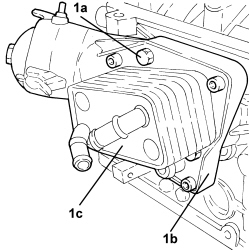
| Water/engine oil heat exchanger support | Bolt | M10 | 4.5 ÷ 5.5 | 1.9 Multijet |
| Component | Fastening | dia | Value (daNm) | Validity |
|---|---|---|---|---|
| Crankshaft oil seal front cover | Bolt (to be replaced) | M6 x 1 x 22 | 0.8 ÷ 1.0 | 1.9 Multijet |
| Component | Fastening | dia | Value (daNm) | Validity |
|---|---|---|---|---|
| Crankshaft oil seal front cover | Bolt | M6 x 1 x 35 | 0.8 ÷ 1.0 | 1.9 Multijet |
| Tool | Description | Function | Validity |
|---|---|---|---|
| 1860816000 | Fitting tool | Fitting oil pump sealing ring | 1.9 Multijet |
| Component | Fastening | dia | Value (daNm) | Validity |
|---|---|---|---|---|
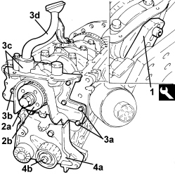
| Toothed drive pulley | Left hand bolt | M16 | 32.3 ÷ 35.7 | 1.9 Multijet |
| Component | Fastening | dia | Value (daNm) | Validity |
|---|---|---|---|---|
| Moving timing system tensioner support | Bolt | M12 | 2.8 ÷ 3.1 + 40° +/- 2° | 1.9 Multijet |
| The sealant strip must be unbroken. |
| When fitting the crankcase sump, take care not to damage the sealant strip. |
| Finish the installation operation within 10 minutes of applying the sealant. |
| Component | Fastening | dia | Value (daNm) | Validity |
|---|---|---|---|---|
| Engine oil sump | Side bolts | M8 | 2.2 ÷ 2.7 | 1.9 Multijet |
| Component | Fastening | dia | Value (daNm) | Validity |
|---|---|---|---|---|
| Engine oil sump | Timing side and gearbox side bolts | M6 | 0.8 ÷ 1.0 | 1.9 Multijet |
| Tool | Description | Function | Validity |
|---|---|---|---|
| 1860833000 | Spanner | Loosen/ tighten the bolts securing the crankcase sump, timing side and gearbox side | 1.9 Multijet |
| Component | Fastening | dia | Value (daNm) | Validity |
|---|---|---|---|---|
| Compressor support | Bolt | M10x1.25x85 | 4.5 ÷ 5.5 | 1.9 Multijet |
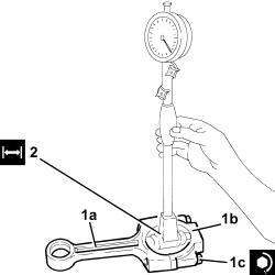
| Tool | Description | Function | Validity |
|---|---|---|---|
| 1820253000 | Dial gauge mount | Measure the piston protrusion/valve recess in relation to the cylinder head plane | 1.9 Multijet |

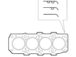
| Measurement | Value | Validity |
|---|---|---|
| Cylinder head gasket size with average maximum piston projection (mm) | projection0.014 ÷ 0.104thickness (no reference)0.770 ÷ 0.870 | 1.9 Multijet |
| Measurement | Value | Validity |
|---|---|---|
| Cylinder head gasket size with average maximum piston projection (mm) | projection0.105 ÷ 0.205thickness (one reference)0.870 ÷ 0.970 | 1.9 Multijet |
| Measurement | Value | Validity |
|---|---|---|
| Cylinder head gasket size with average maximum piston projection (mm) | projection0.206 ÷ 0.294thickness (two references)0.970 ÷ 1.070 | 1.9 Multijet |
| The cylinder head gasket is ASTADUR type. The material from which the gasket is made undergoes a polymerization process during the operation of the engine so that it becomes considerably harder during usage. In order for the polymerization process to take place, it is necessary to:- keep the gasket sealed in its casing until it is fitted;- not lubricate the gasket or the contact surfaces with oil. |
| Component | Fastening | dia | Value (daNm) | Validity |
|---|---|---|---|---|
| Cylinder head | Bolt | M12 | 6.5 + 90° + 90° + 90° | 1.9 Multijet |
| Tool | Description | Function | Validity |
|---|---|---|---|
| 1860942000 | Torque wrench | Tighten bolts to torque plus angle |
| Achieve the figure of 6.5 daNm by a pretightening of 2.0 daNm subsequently increased by a torque of 4.5 daNm to achieve a nominal value of 6.5 daNm |

| Follow the order shown in the diagram for each tightening sequence. |

| Component | Fastening | dia | Value (daNm) | Validity |
|---|---|---|---|---|
| Tappet cover | Bolt | M6 | 0.8 ÷ 1.0 | 1.2 8v1.4 8v1.3 Multijet1.9 Multijet |
| Component | Fastening | dia | Value (daNm) | Validity |
|---|---|---|---|---|
| Pressure pump mounting | Bolt (to be replaced) | M8 | 2.3 ÷ 2.8 | 1.9 Multijet |
| Component | Fastening | dia | Value (daNm) | Validity |
|---|---|---|---|---|
| Pipe from pressure pump to fuel manifold - fuel manifold side | Connector | M14 | 2.2 ÷ 2.4 | 1.9 Multijet |
| Component | Fastening | dia | Value (daNm) | Validity |
|---|---|---|---|---|
| Pipe from pressure pump to fuel manifold - pressure pump side | Connector | M12 | 2.2 ÷ 2.4 | 1.9 Multijet |
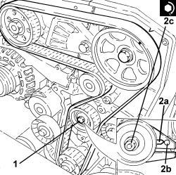
| The crankshaft must be rotated, using small movements, to allow the locating dowel on the timing drive pulley to be inserted in the opening in the tool. |
| Tool | Description | Function | Validity |
|---|---|---|---|
| 2000003000 | Template | Engine tuning | 1.9 Multijet |
| Component | Fastening | dia | Value (daNm) | Validity |
|---|---|---|---|---|
| Moving timing system tensioner | Nut | M8 | 2.3 ÷ 2.8 | 1.9 Multijet |

| Component | Fastening | dia | Value (daNm) | Validity |
|---|---|---|---|---|
| Moving timing system tensioner | Nut | M8 | 2.3 ÷ 2.8 | 1.9 Multijet |
| Component | Fastening | dia | Value (daNm) | Validity |
|---|---|---|---|---|
| Timing side power unit rigid support to engine block | Bolt | M10 | 4.5 ÷ 5.5 | 1.9 Multijet |
| Component | Fastening | dia | Value (daNm) | Validity |
|---|---|---|---|---|
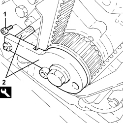
| Auxiliary drive belt fixed tensioner | Bolt | M8 | 2.2 ÷ 2.7 | 1.9 Multijet |
| Component | Fastening | dia | Value (daNm) | Validity |
|---|---|---|---|---|
| Services pulley on crankshaft | Bolt | M8 | 2.3 ÷ 2.8 |
| Component | Fastening | dia | Value (daNm) | Validity |
|---|---|---|---|---|
| Turbocharger assembly and exhaust manifold - cylinder head side | Nut | M8 | 2.2 ÷ 2.7 | 1.9 Multijet |
| Component | Fastening | dia | Value (daNm) | Validity |
|---|---|---|---|---|
| Engine oil return pipe from turbocharger - crankcase side | Bolt | M8 | 2.2 ÷ 2.7 | 1.9 Multijet |
| Component | Fastening | dia | Value (daNm) | Validity |
|---|---|---|---|---|
| Engine oil supply pipe to turbocharger - crankcase side | Connector | M12 | 2.2 ÷ 2.7 | 1.9 Multijet |