| STEP | CHECK TO BE PERFORMED | RESOLUTION IF THE CHECK IS NOT OK |
|---|
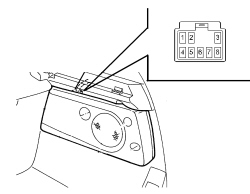
| 1 | Check power supply (+30)- Check for battery voltage across pin 3 of the subwoofer connector and earth- Check that the connector is correctly inserted in its other part- Try to move it from its seat by making small movements in all directions, grasping the connector body in your fingers and the wiring in your hand. The connector must stay in place- Exercise a moderate pulling force. The connector must stay in place- Check whether the power supply goes off, on and/or viceversa (touching/not touching)- Pull the lead and check the stability in the groove (should not move back): exercise repeated pull-push-pull cycles on the cable and check it remains immobileExamine the crimping.Use a lens to examine the terminal crimping area. The barrels must be turned symmetrically and no strands should emerge from the crimped area. The bare wire section under the barrels must emerge by 0.5. | Restore correct power supply See E3510 RADIO |
| 2 | Check the earthDisconnect the subwoofer connector and connect an ohmmeter accross pin 7 and earth and check the resistance is lower than 1 ohm | Restore the earth connection |
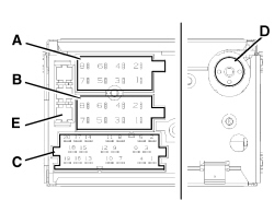
| 3 | Check the ignition signalWith the radio on, check for a 12 Volt signal at pin 8 of the subwoofer connector | Restore the connection between the subwoofer and audio amplifier See E3510 RADIO If the wiring is OK, continue to step 4 and replace the radio if the radio output power supply is interrupted |
| 4 | Check the subwoofer enablement signalWith the radio on, check for a 12 Volt signal at pin 6 of radio connector C | Replace the radio Op. 5570T80 CAR RADIO EQUIPMENT - R+R |