199000423 - 1016C10 SINGLE CYLINDER HEAD - R.R. AND REPLACE GASKET

Removing
(
Refitting
)
- Position the vehicle on a lift. Op. 1016A10 SOUND-PROOFING COVER - R.R Op. 5530B10 BATTERY - R+R Op. 5530B52 BATTERY SUPPORT/DRIP TRAY - R.R Op. 0010T20 ENGINE COOLANT - CHANGE Op. 1048A10 AIR FILTER ASSEMBLY - R.R. Op. 7055B54 UNDER ENGINE PROTECTION/GUARD - R.R. Op. 4450B04 RIGHT FRONT WHEEL - R.R Op. 7055B66 ENGINE COMPARTMENT DUST COVER IN RIGHT FRONT WHEEL ARCH - R.R. Op. 1092G10 SINGLE ENGINE BELT - R.R Op. 1092A10 CRANKSHAFT PULLEY - R + R Op. 1076B72 INTERMEDIATE EXHAUST PIPE WITH HOSE SECTION - R+R
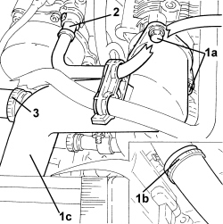
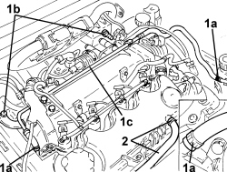
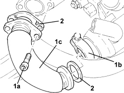
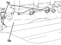
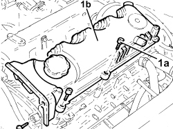
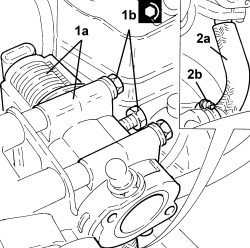
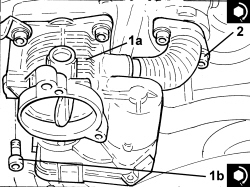
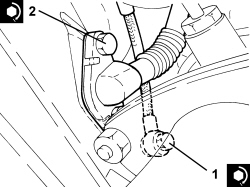
1. Undo bolts (1a), loosen band (1b) and remove throttle body rigid air inlet pipe (1c).2. Disconnect from the vacuum pump the rapid connector for the vacuum intake pipe.3.Loosen the band and disconnect the radiator upper coolant inlet hose, thermostat side.
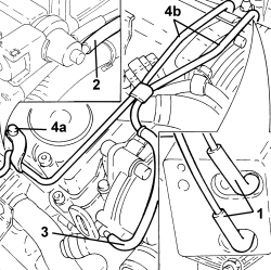
1. Disconnect the vacuum pipes from the vacuum reservoir.2. Disconnect the vacuum pipe from the turbocharger vane position actuator control solenoid valve.3. Disconnect the vacuum pipe from the vacuum pump.4. Undo fastenings (4a) and remove vacuum pipes (4b).
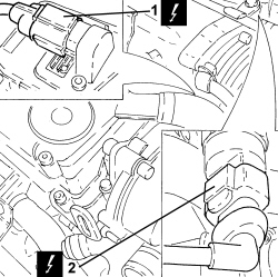
1. Detach the electrical connection from the throttle casing.2. Detach the electrical connection from the fuel pressure sensor on the fuel manifold.
1. Detach the electrical connection from the engine coolant temperature sensor.2. Loosen the band and disconnect the coolant return pipe to the engine coolant reservoir, thermostat side.
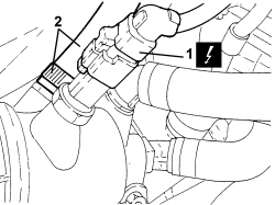
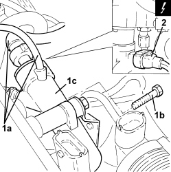
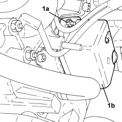
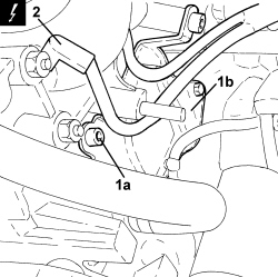
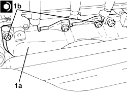
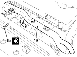
1. Loosen bands (1a), undo bolts (1b) and remove coolant return pipe to engine coolant supply reservoir (1c).2. Loosen the band and disconnect the oil vapour pipes from the tappet cover.
1. Detach the electrical connection from the E.G.R. system solenoid2. Detach the electrical connection from the pressure relief sensor.
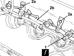
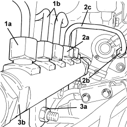
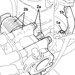
1. Detach the electrical connections from the injectors.2. Undo bolts (2a) and move electrical wiring (2b) aside.
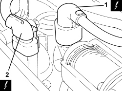
1. Disconnect pipes (1a), undo bolts (1b), then remove fuel return manifold (1c).2. Detach the electrical connection from the fuel pressure regulator on the pressure pump.
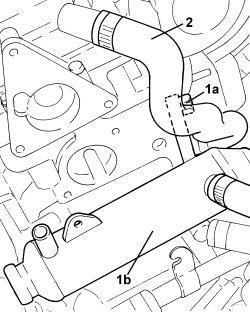
1. Manually push clips (1a) and disconnect pipe from injectors to fuel recovery manifold (1b), injector side, and remove it.2. Undo the connectors securing the pipes from the fuel manifold to the injectors, injector side.
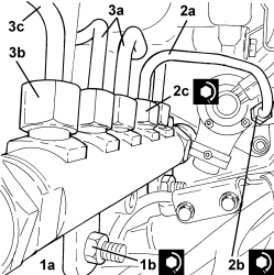
1. Unscrew connectors (1a) and remove pipes from fuel manifold to injectors (1b).2. Undo connectors (2a) and (2b) and remove pipe from pressure pump to fuel manifold (2c).3. Undo nuts (3a) and remove single fuel manifold pipe assembly (3b).
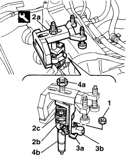
1. Undo the nuts fixing the injector mounting brackets.2. Position tool (2a) for extracting the injectors, taking care to position lifting bracket (2b) under polygonal area (2c) of the injector.| Tool | Description | Function | Validity |
|---|
| 1870739000 | Extractor | Removing injectors | 1.3 Multijet1.9 Multijet |
3. Position second lifting bracket for tool (3a) under injector securing bracket (3b).4. Tighten nut for tool (4a) and remove injector assembly (4b).- Repeat the operation for the remaining injectors.
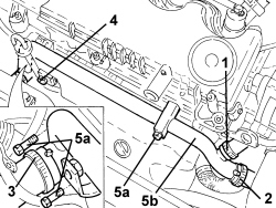
1. Loosen the band and disconnect the coolant outlet pipe from the coolant/exhaust gas heat exchanger for the EGR system.2. Loosen the band and disconnect the coolant return pipe from the engine oil heat exchanger on the water pump rigid inlet pipe side.3. Loosen the band and disconnect the lower coolant inlet hose from the radiator, water pump rigid coolant inlet pipe side.4. Undo the upper bolt securing the engine oil dipstick tube.5. Undo bolts (5a) and remove water pump inlet pipe (5b).- Remove the gasket.
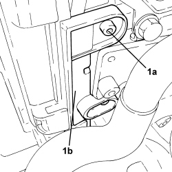
1. Undo bolts (1a) and remove side guard (1b) for the timing belt.
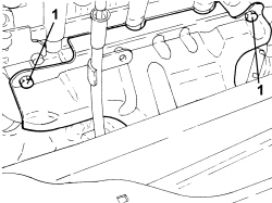
1. Undo the two upper bolts fixing the exhaust manifold heat shield.
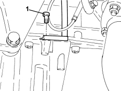
1. Undo the lower bolt securing the engine oil dipstick tube.
1. Undo nuts (1a) and bolt (1b) securing the exhaust manifold heat shield.
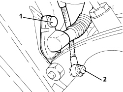
- Working via the engine compartment, remove the pipe for the engine oil dipstick and the exhaust manifold heat shield.1. Undo the bolts securing the engine oil return pipe from the turbocharger, engine block side.2. Undo the connector fastening the engine oil supply pipe to the turbocharger, engine block side.
1. Undo bolts (1a), loosen collar (1b) and remove exhaust gas intake pipe from the exhaust manifold to the E.G.R. heat exchanger (1c).2. Remove the associated seals.
1. Undo nuts (1a) and move turbocharger and exhaust manifold assembly (1b) away from the cylinder head.
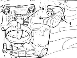
1. Undo the bolts fixing the exhaust gas outlet hose from the E.G.R. solenoid valve, E.G.R. solenoid valve side.2. Undo bolts (2a) and remove throttle body (2b).- Remove the gasket.
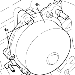
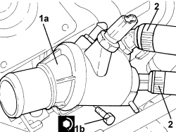
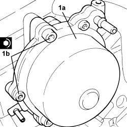
1. Undo bolts (1a) and remove vacuum unit (1b).- Remove the gasket.
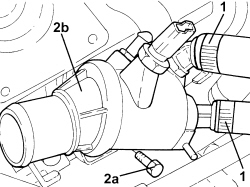
1. Loosen the bands and disconnect the pipes from the thermostat.2. Undo bolts (2a) and remove thermostat (2b).- Remove the gasket.
1. Loosen collar (1a) and disconnect exhaust gas outlet hose from exhaust gas/water heat exchanger for E.G.R. system (1b), heat exchanger side.2. Undo bolts (2a) and remove E.G.R. system solenoid (2b), complete with hose.- Remove the gasket.
1. Undo fastenings (1a) and remove water/exhaust gas heat exchanger for E.G.R. system (1b).2. Loosen the band and disconnect the oil vapour pipe from the tappet cover to the crankcase, tappet cover side.
1. Undo nuts (1a) and remove vacuum reservoir for engine air intake management (1b).
1. Undo fastenings (1a) and remove vacuum reservoir mounting (1b).2. Detach the electrical connections from the heater plugs.
1. Undo bolts (1a) and remove cam cover (1b) complete with gasket.
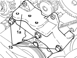
Op. 1008B10 POWER UNIT FRONT SUPPORT FLEXIBLE MOUNTING (TIMING SIDE) - REPLACE Op. 1032D12 TIMING SYSTEM PROTECTIVE COVER(S) - R + R Op. 1092G20 ENGINE COMPONENT SINGLE BELT FIXED TENSIONER - R + R Op. 1008A46 POWER UNIT RIGID SUPPORT - TIMING SIDE - R.R. Op. 1032B10 TOOTHED TIMING BELT - R + R FOR TIMING ADJUSTMENT OR REPLACEMENT 1. Fit timing side power unit rigid support (1a) temporarily in its housing and secure it using bolts (1b).
- Fit the timing side power unit front support flexible mounting temporarily in its housing and secure it using the bolts.- Remove the hydraulic jack from underneath the engine.
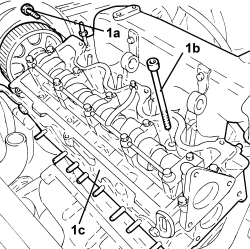
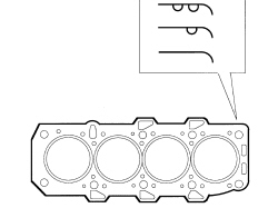
1. Undo bolts (1a) and (1b), then remove cylinder head (1c).2. Remove the cylinder head gasket.
- To check the flatness of the lower cylinder head surface and grind if necessary, refer to Op. 1016E10 SINGLE CYLINDER HEAD, REMOVED - OVERHAUL
Refitting
(
Removing
)
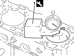
1. Measure the piston projection in two places at 180° on the gudgeon pin axis using the tool and take the average of the two values measured for each piston.| Tool | Description | Function | Validity |
|---|
| 1820253000 | Dial gauge mount | Measure the piston protrusion/valve recess in relation to the cylinder head plane | 1.9 Multijet |
- Select the correct size cylinder head gasket, according to the maximum value of the averages for the projection for each individual piston.| Measurement | Value | Validity |
|---|
| Cylinder head gasket size with average maximum piston projection (mm) | projection0.014 ÷ 0.104thickness (no reference)0.770 ÷ 0.870 | 1.9 Multijet |
| Measurement | Value | Validity |
|---|
| Cylinder head gasket size with average maximum piston projection (mm) | projection0.105 ÷ 0.205thickness (one reference)0.870 ÷ 0.970 | 1.9 Multijet |
| Measurement | Value | Validity |
|---|
| Cylinder head gasket size with average maximum piston projection (mm) | projection0.206 ÷ 0.294thickness (two references)0.970 ÷ 1.070 | 1.9 Multijet |
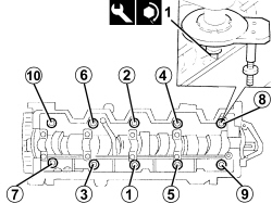
- Place the cylinder head centering bushes on the cylinder block.- Refit the new cylinder head gasket in its seat.- Position the cylinder head on the cylinder block/crankcase.1. Tighten the bolts securing the cylinder head to the cylinder block to the recommended torque, following the order illustrated and using the angular tightening tool.| Component | Fastening | dia | Value (daNm) | Validity |
|---|
| Cylinder head | Bolt | M12 | 6.5 + 90° + 90° + 90° | 1.9 Multijet |
| Tool | Description | Function | Validity |
|---|
| 1860942000 | Torque wrench | Tighten bolts to torque plus angle | |
- Tighten to the recommended torque the new bolt fixing the pressure pump mounting to the cylinder head.| Component | Fastening | dia | Value (daNm) | Validity |
|---|
| Pressure pump mounting | Bolt (to be replaced) | M8 | 2.3 ÷ 2.8 | 1.9 Multijet |
- Position a hydraulic jack underneath the engine.- Remove the provisionally fitted flexible mounting for the timing side power unit front support.- Remove the timing side rigid power unit support fitted provisionally.
Op. 1032B10 TOOTHED TIMING BELT - R + R FOR TIMING ADJUSTMENT OR REPLACEMENT Op. 1008A46 POWER UNIT RIGID SUPPORT - TIMING SIDE - R.R. Op. 1092G20 ENGINE COMPONENT SINGLE BELT FIXED TENSIONER - R + R Op. 1032D12 TIMING SYSTEM PROTECTIVE COVER(S) - R + R Op. 1008B10 POWER UNIT FRONT SUPPORT FLEXIBLE MOUNTING (TIMING SIDE) - REPLACE - Place the tappet cover in position and secure it by tightening the bolts to the recommended torque.| Component | Fastening | dia | Value (daNm) | Validity |
|---|
| Tappet cover | Bolt | M6 | 0.8 ÷ 1.0 | 1.2 8v1.4 8v1.3 Multijet1.9 Multijet |
- Secure the electrical connections to the heater plugs.-- Place the vacuum reservoir mounting back in its housing and secure it.- Place the vacuum reservoir for the engine air intake management back in its housing and secure it using the nuts.- Connect the oil vapour pipe from the tappet cover to the crankcase, tappet cover side, and tighten the band.- Place the exhaust gas/water heat exchanger for the E.G.R. system back in its housing and secure it.- Place the gasket for the E.G.R. system solenoid valve in its housing.1. Place E.G.R. system solenoid (1a) complete with hose in its housing and fasten it by tightening bolts (1b) to the recommended torque.| Component | Fastening | dia | Value (daNm) | Validity |
|---|
| E.G.R. system solenoid | Bolt | M8 | 2.3 ÷ 2.8 | 1.9 Multijet |
2. Connect the exhaust gas outlet hose from the exhaust gas/water heat exchanger for the E.G.R. system (2a), heat exchanger side, and tighten collar (2b).
- Place the gasket for the thermostat back in its housing.1. Place thermostat (1a) in its housing and fasten it by tightening bolts (1b) to the recommended torque.| Component | Fastening | dia | Value (daNm) | Validity |
|---|
| Thermostat | Bolt | M8 | 2.2 ÷ 2.7 | 1.3 Multijet1.9 Multijet |
2. Connect the pipes to the thermostat and tighten the bands.
- Place the gasket for the vacuum unit back in its housing.1. Place vacuum unit (1a) in its housing and fasten it by tightening bolts (1b) to the recommended torque.| Component | Fastening | dia | Value (daNm) | Validity |
|---|
| Vacuum pump | Bolt | M8 | 2.7 ÷ 3.3 | 1.9 Multijet |
- Place the gasket for the throttle body back in its housing.1. Place throttle body (1a) in its housing and secure it by tightening bolts (1b) to the recommended torque.| Component | Fastening | dia | Value (daNm) | Validity |
|---|
| Throttle body | Bolt | - | - | 1.9 Multijet |
2. Tighten the bolts fixing the exhaust gas outlet hose from the E.G.R. solenoid valve, E.G.R. solenoid valve side.
1. Place turbocharger and exhaust manifold assembly (1a) in its housing and tighten nuts (1b) to the recommended torque.| Component | Fastening | dia | Value (daNm) | Validity |
|---|
| Turbocharger assembly and exhaust manifold - cylinder head side | Nut | M8 | 2.2 ÷ 2.7 | 1.9 Multijet |
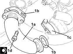
1. Place exhaust gas intake pipe from exhaust manifold to E.G.R. heat exchanger (1a) back in its housing, complete with gaskets (1b), then secure it by tightening collar (1c) and bolts (1d) to the recommended torque.| Component | Fastening | dia | Value (daNm) | Validity |
|---|
| Exhaust gas/water heat exchanger for E.G.R. system | Bolt | M8 | 2.3 ÷ 2.8 | 1.3 Multijet1.9 Multijet |
1. Tighten the connector securing the engine oil delivery pipe to the turbocharger, crankcase side, to the recommended torque.| Component | Fastening | dia | Value (daNm) | Validity |
|---|
| Engine oil supply pipe to turbocharger - crankcase side | Connector | M12 | 2.2 ÷ 2.7 | 1.9 Multijet |
2. Tighten the bolts securing the engine oil return pipe from the turbocharger, crankcase side, to the specified torque.| Component | Fastening | dia | Value (daNm) | Validity |
|---|
| Engine oil return pipe from turbocharger - crankcase side | Bolt | M8 | 2.2 ÷ 2.7 | 1.9 Multijet |
- Working via the engine compartment, place the pipe for the engine oil dipstick and the exhaust manifold heat shield in their housings.- Tighten the lower nuts and the bolt securing the exhaust manifold heat shield.- Tighten the lower bolt securing the engine oil dipstick tube.- Tighten the two upper bolts fixing the exhaust manifold heat shield.- Place the water pump rigid inlet pipe gasket in its housing.1. Place water pump rigid inlet pipe (1a) in position and secure it by tightening bolts (1b) to the recommended torque.| Component | Fastening | dia | Value (daNm) | Validity |
|---|
| Water pump rigid inlet pipe | Bolt | M6 | 0.8 ÷ 1.0 | 1.9 Multijet |
- Fit the timing belt side protective cover and secure it using the bolts.- Tighten the upper bolt securing the engine oil dipstick tube.- Connect the lower coolant inlet hose from the radiator, water pump rigid coolant inlet pipe side, and tighten the band.- Connect the return pipe from the engine oil heat exchanger, water pump rigid inlet pipe, and tighten the band.- Connect the coolant oulet pipe from the coolant/exhaust gas heat exchanger for the EGR system and tighten the band.- Place the injectors in their seats, complete with brackets, and fasten them by tightening the nuts to the recommended torque.| Component | Fastening | dia | Value (daNm) | Validity |
|---|
| Injector brackets | Nut | M8 | 2.7 ÷ 3.3 | 1.9 Multijet |
1. Place single fuel manifold pipe (1a) in its housing and secure it by tightening nuts (1b) to the recommended torque.| Component | Fastening | dia | Value (daNm) | Validity |
|---|
| Common rail | Nut | M8 | 2.3 ÷ 2.8 | 1.9 Multijet |
2. Place pipe from pressure pump to fuel manifold pipe (2a) back in its housing and secure it by tightening connectors (2b) and (2c) to the recommended torque.| Component | Fastening | dia | Value (daNm) | Validity |
|---|
| Pipe from pressure pump to fuel manifold - pressure pump side | Connector | M12 | 2.2 ÷ 2.4 | 1.9 Multijet |
| Component | Fastening | dia | Value (daNm) | Validity |
|---|
| Tubazione da pompa di pressione a collettore combustibile | Raccordo | M14 | (lato collettore combustibile) 2.2 ÷ 2.4 | 1.9 JTD 8v |
| Component | Fastening | dia | Value (daNm) | Validity |
|---|
| Pipe from pressure pump to fuel manifold - fuel manifold side | Connector | M14 | 2.2 ÷ 2.4 | 1.9 Multijet |
3. Place pipes from fuel manifold to injectors (3a) in their housings and secure them by tightening connectors (3b) and (3c) to the recommended torque.| Component | Fastening | dia | Value (daNm) | Validity |
|---|
| Pipes from fuel manifold to injectors - fuel manifold side | Connector | M14 | 2.2 ÷ 2.4 | 1.9 Multijet |
| Component | Fastening | dia | Value (daNm) | Validity |
|---|
| Pipes from fuel manifold to injectors - injectors side | Connector | M12 | 2.2 ÷ 2.4 | 1.9 Multijet |
- Place the pipe from the injectors to the fuel recovery manifold in its housing, connect it to the injectors and push home until the clips click into place.- Attach the electrical connection to the fuel pressure regulator on the pressure pump.- Place the fuel return manifold in its housing, secure it using the bolts and connect the pipes.- Place the electrical wiring in position and fasten it using the bolts.- Secure the electrical connections to the injectors.- Secure the electrical connection for the pressure relief sensor.- Secure the electrical connection to the EGR system solenoid- Connect the engine oil vapour recovery pipe to the tappet cover.- Place the coolant return pipe to the engine coolant reservoir in position and secure it using the bolts. Then tighten the bands.- Secure the electrical connection to the engine coolant temperature sensor.- Secure the electrical connection to the fuel pressure sensor on the fuel manifold.- Secure the electrical connection to the throttle casing.- Place the vacuum pipes in their housings and secure them.- Connect the vacuum pipe to the vacuum unit.- Connect the vacuum pipe to the turbocharger vane position actuator control solenoid valve.- Connect the vacuum pipes to the vacuum reservoir.- Connect the radiator upper coolant inlet hose, thermostat side, and tighten the band.- Connect the vacuum pipe rapid connector to the vacuum pump.- Place the hose and the throttle body rigid air inlet pipe in their housings, then fasten them using the band and the bolts.- Tighten the coolant drain plug to the radiator. Op. 1076B72 INTERMEDIATE EXHAUST PIPE WITH HOSE SECTION - R+R Op. 1092A10 CRANKSHAFT PULLEY - R + R Op. 1092G10 SINGLE ENGINE BELT - R.R Op. 7055B66 ENGINE COMPARTMENT DUST COVER IN RIGHT FRONT WHEEL ARCH - R.R. Op. 4450B04 RIGHT FRONT WHEEL - R.R Op. 1048A10 AIR FILTER ASSEMBLY - R.R. Op. 5530B52 BATTERY SUPPORT/DRIP TRAY - R.R Op. 5530B10 BATTERY - R+R Op. 1016A10 SOUND-PROOFING COVER - R.R Op. 0010T20 ENGINE COOLANT - CHANGE Op. 7055B54 UNDER ENGINE PROTECTION/GUARD - R.R. - Remove the vehicle from the lift.