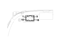
| Pin | SIGNAL |
|---|
| 1 | Earth |
| 2 | Battery (+ 30) |
| 3 | Key (+ 15) |
| 4 | N.C. |
| 5 | CAN A |
| 6 | CAN B |
| 7 | Reference signal for headlamp alignment actuators |
| 8 | + dipped headlamps signal for headlamp alignment corrector control |
| 9 | Negative signal from trip button on steering wheel stalk unit |
| 10 | Input for warning light available |
| 11 | N.C. |
| 12 | N.C. |
| 13 | Control signal from “MODE +” panel |
| 14 | Signal from headlamp alignment corrector panel |
| 15 | Safety acoustic signal activation negative command from NCR |
| 16 | Control signal from “MODE -” panel |
| 17 | Warning light input available |
| 18 | I.E./EOBD failure warning light negative signal from NCM |