199000456 - 1032B10 TOOTHED TIMING BELT - R + R FOR TIMING ADJUSTMENT OR REPLACEMENT
| Tool | Description | Function | Validity |
|---|---|---|---|
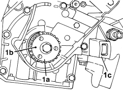
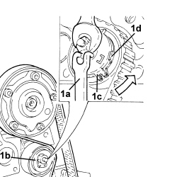
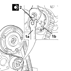
| 1860985000 | Locating pins | Camshaft timing | 1.4 16v |
| Description | Connector | |
|---|---|---|
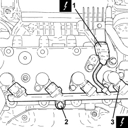
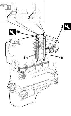
| 1 | Absolute pressure sensor | See K048 ABSOLUTE PRESSURE SENSOR |
| Description | Connector | |
|---|---|---|
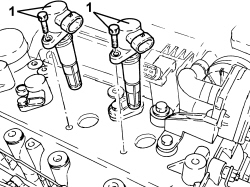
| 3 | Ignition coil | See A030 IGNITION COIL |
| Tool | Description | Function | Validity |
|---|---|---|---|
| 1860992000 | Bearings | Crankshaft timing | 1.4 16v |
| Rotate the crankshaft proceeding gradually to prevent the tool pins being expelled by the compression of the pistons. |
| Tool | Description | Function | Validity |
|---|---|---|---|
| 1860985000 | Locating pins | Camshaft timing | 1.4 16v |
| Tool | Description | Function | Validity |
|---|---|---|---|
| 2000015800 | Counter-torque | Camshaft driven pulley lock | 1.4 16v |
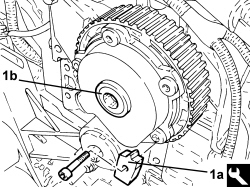
| Ensure that this operation is performed with the driven pulley/phase transformer slack. |
| Tool | Description | Function | Validity |
|---|---|---|---|
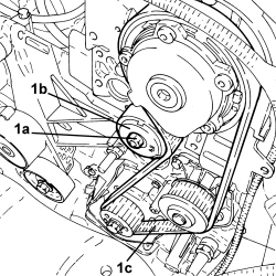
| 1860987000 | Spanner | Tensioning toothed timing drive belt | 1.2 8v1.4 8v1.4 16v |
| Component | Fastening | dia | Value (daNm) | Validity |
|---|---|---|---|---|
| Driven timing pulley | Bolt | M12 | 10.8 ÷ 13.2 | 1.4 16v |
| Component | Fastening | dia | Value (daNm) | Validity |
|---|---|---|---|---|
| Moving timing system tensioner | Nut | M8 | 2.2 ÷ 2.7 | 1.4 16v |
| Component | Fastening | dia | Value (daNm) | Validity |
|---|---|---|---|---|
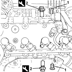
| Engine cylinder head extension plugs | - | M16 | 1.3 ÷ 1.6 | 1.4 16v |
| Component | Fastening | dia | Value (daNm) | Validity |
|---|---|---|---|---|
| Spark plugs | - | M12 | 1.6 ÷ 2.0 | 1.4 16v |
| Component | Fastening | dia | Value (daNm) | Validity |
|---|---|---|---|---|
| Ignition coils | Bolt | M6 | 0.8 ÷ 1.0 | 1.2 8v1.4 8v1.4 16v |