199002367 - 1072B50 AIR CHAMBER - R.R.
| If the air chamber is replaced, run the following self-learning procedure. |
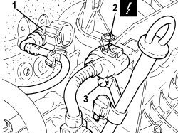
| Description | Connector | |
|---|---|---|
| 2 | Air pressure - temperature sensor | See K044 AIR PRESSURE - TEMPERATURE SENSOR |
| Description | Connector | |
|---|---|---|
| 1 | Absolute pressure sensor | See K048 ABSOLUTE PRESSURE SENSOR |
| Description | Connector | |
|---|---|---|
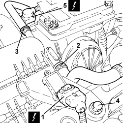
| 5 | Fuel vapour recovery solenoid valve | See L010 FUEL VAPOUR RECOVERY SOLENOID VALVE |
| Description | Connector | |
|---|---|---|
| 1 | Engine management control unit | See M010 ENGINE MANAGEMENT ECU |
| Description | Connector | |
|---|---|---|
| 2 | Injection control unit earth | See C060 INJECTION CONTROL UNIT EARTH |

| Description | Connector | |
|---|---|---|
| 1 |
| Description | Connector | |
|---|---|---|
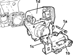
| 2 | Integrated throttle body actuator | See N075 BUILT-IN THROTTLE BODY ACTUATOR |

| Description | Connector | |
|---|---|---|
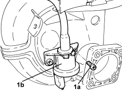
| 1 | PDA solenoid valve | See L031 PDA SOLENOID VALVE |


| Component | Fastening | dia | Value (daNm) | Validity |
|---|---|---|---|---|
| Intake manifold - cylinder head side | Bolt (to be replaced) | M7 | 1.3 ÷ 1.6 | 1.4 16v |
| Component | Fastening | dia | Value (daNm) | Validity |
|---|---|---|---|---|
| Intake manifold - cylinder head extension side | Bolt (to be replaced) | M6 | 0.8 ÷ 1.1 | 1.4 16v |