199000614 - 5540 EXTERIOR LIGHTING
COMPOSITION
The vehicle exterior lighting system has been designed and produced with two objectives in mind:- guaranteeing maximum efficiency with regard to the international regulations that define the lighting technology specifications for the various components;- being integrated with the design of the vehicle so that the various components enhance the image.Location of components on vehicle
The vehicle components and their location are illustrated below.1 - Right front light cluster2 - Left front light cluster3 - Left fog light4 - Right fog light5 - Left front direction indicator6 - Right front direction indicator7 - Right rear light cluster8 - Right rear light cluster9 - Rear fog lamp10 - Reversing light11 - Third brake light12 - Number plate lightsFront light cluster
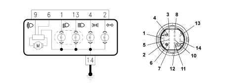
The unit consists of:1 - Side light2 - Dipped/main beam headlamp3 - Direction indicatorBulbs present:- Halogen H4 55W - 12V for double filament dipped/main beam headlamps function- All glass W5W 12V for side lights function- All glass PY21W - 12V for direction indicators function - 12V-21WWiring diagram and connector
PIN OUT:1- Dipped headlamps control2 - Direction indicators control4 - Side lights control6 - Power supply for headlamp alignment corrector9 - Headlamp alignment correction signal13 - Main beam headlamps control14 - Earth connectionElectrically controlled headlamp alignment corrector
The headlamp alignment device is designed to adjust dipped light beam correctly in a vertical direction irrespective of the load on the axles.With the dipped headlamps on, using the buttons on the left side of the control panel, it is possible to alter the angle/direction of the light cluster in 4 standard positions: the following loads correspond to the four positions:0 - 1 person (driver), 2 persons (in the front seats)1 - 5 persons, 2 persons (in the front seats), 3 persons (in the rear seats)2 - 5 persons plus maximum load3 - 1 person (driver) plus maximum permitted load in luggage compartment without rear seat folded downThe maximum load refers to: the maximum permitted load on the rear axle or: the total permitted load for the vehicle. The weight of a person is taken as 75 kg.The instrument panel display shows the position in relation to the adjustment set. See descriptions 5560 INSTRUMENTS The headlamp incorporates an electric motor: the latter controls the position by means of a pinion and an adjustment screw suitably tilting the dipped headlamp reflector.1 - electric motor2 - dipped headlamp reflectorRear light cluster
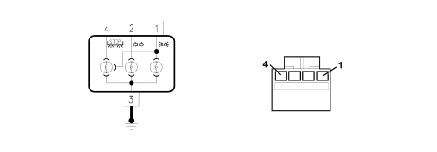
The rear light cluster is divided into two parts, one fixed outer one and one moving one on the boot.The following signals are contained in the light cluster on the fixed part:- Red brake lights and side lights (double filament).- White direction indicator and orange reflector.- White side light and red reflector.The unit in the bumper contains:- Red rear fog lamp (driver''s side only).- White reversing light (passenger side only).The outer unit consists of:1 - Direction indicator2 - Brake/side light3 - Side lightC - connectorBulbs present:- Direction indicator: P21W - 12V- Side light: R5W - 12V- Side/brake light: bilux P21W-5W - 12VWiring diagram and connector
PIN OUT:1 - Side lights control2 - Direction indicators control3 - Earth connection4 - Brake light controlThe two symmetrical units located in the bumper contain the red rear fog lamp P21W - 12V (driver''s side) and the white reversing light P21W - 12W (passenger side).1 - rear fog lamp2 - reversing lightNumber plate light
The number plate light function is achieved by means of two lights fitted using a metal clip and a catch projection fastened to the trim.Each light is fitted with an all glass 12V - 5W bulb and it should be replaced by removing the light from the trim and the bulb holder from the number plate light, incorporated in the wiring in the rear bumper.1 - Casing2 - Lens cover3 - Clip4 - Bulb holder5 - Seal6 - All glass bulb 12V - 5WDirection indicators side repeater
To replace the small bulb, push the lens cover manually in the direction of travel in order to compress the fastening clip (5). Release the front section and extract the assembly. Rotate the bulb holder in an anti-clockwise direction and extract it from the lens cover.1 - Grey casing2 - Lens cover3 - Bulb 12V - 5W (orange)4 - Bulb holder5 - Fastening clipAdditional (third) brake light
The function of the additional brake light is produced through the multibulb lamp and light beam coming from the rearscreen serigraphy.The casing is made from black coloured bayblend and contains the bulb holder which is in one piece and is fastened to the actual casing. The internal current tracks are made from coppper-covered brass and, with the circuit activated, supply 8 small all glass type 12V - 2.3W bulbs.The light has two housings for the fastening. The red coloured metacrylate lens cover is fitted on the light casing and its shape and contours are such that when the light is switched off it produces a masking effect if looked at from the outside of the vehicle.1- Connector2 - Parabola casing3 - (Red) lens cover | The third brake light includes the wiping function (jet for detergent fluid). |
Fog lights
The fog lights are located in the lower part of the front bumper. The unit has a screw for adjusting the direction of the light beam.1 - Lamp casing2 - Adjustment screwThe bulb used for the fog lights function is a halogen H1 type bulb, 12V - 55W.OPERATION
The management of the operation of all the exterior lights is carried out by the Body Computer.Side lights
When the user switches on the side lights (with the ignition ON) or requests "Parking lights" or "Follow Me Home" (with the ignition OFF), the Body Computer controls the activation of all the side light bulbs (left/right, front and rear).The fault diagnosis carried out by the Body Computer recognizes a fault in the case of an open circuit in one of the front lights or in two of the rear lights. When a fault with a bulb is recognized, the Body Computer signals the side lights failure warning (at the Key ON).No. plate lights
Two no. plate light bulbs are switched on when there is a request to switch on the side lights or "Parking lights". (NOT in the Follow Me Home function).The fault diagnosis is carried out for each individual no. plate light bulb when the control is activated, with a possible "no. plate lights failure" signal in the instrument panel (at the key ON).Parking lights
This function makes it possible to switch on the side lights and the no. plate lights with the ignition OFF, to signal the presence of the vehicle whilst it is parked.The activation only takes place at the key OFF by manoeuvring the steering column switch unit ring nut.The function is deactivated by moving the steering column switch unit lights ring nut to the OFF position or at the vehicle Key ON.This last operation resets the function and the Body Computer controls the lights depending on the command selected using the steering column switch unit ring nut.Dipped headlamps
With the dipped headlamps on, the presence of the main beam control disables the dipped headlamps.The subsequent deactivation of the main beam headlamps control, with the dipped headlamps control activated, switches the dipped headlamps back on.The dipped headlamps also come on with the Follow me home function control described below.Follow me home
This function makes it possible to control the side lights and dipped headlamps for a timed period on leaving the vehicle.The function can be activated within 2 minutes of the Key OFF using the steering column switch unit flasher control.This timed period can be increased: each time the flasher is operated, with the Body Computer increasing the time that the lights remain on up to a maximum of 210 seconds (for a maximum of 7 operations).Operating the flasher control for longer than 2 seconds causes the deactivation of the function with the side lights and dipped headlamps switching off.After deactivation, the follow me hom function can be activated again using the flasher lever within 2 minutes of the Key OFF.A Key ON with the Follow Me Home function activated causes it to be deactivated.Direction indicators/hazard warning lights
Following the direction indicator commands using the left steering column switch unit lever, with the Key ON, the Body Computer operates the direction indicator bulbs individually on the side of the vehicle selected (left front, side and rear or right front, side and rear).When the lever is returned to the rest position, the lights and the other direction indicators go out.If the direction indicators are on, they go out at the Key OFF.At the same time as the operation of the bulbs, there is an acoustic signal from the buzzer inside the instrument panel. See descriptions 5560 INSTRUMENTS At the operation of the hazard warning lights, at both the Key ON or Key OFF, the Body Computer operates all 6 direction indicator bulbs (front, side and rear, left and right) with the activation of the LED in the hazard warning lights button and the acoustic signal inside the passenger compartment as well.If the hazard warning lights button is activated with the direction indicators, the lights/indicators already activated continue to operate intermittently without an interruption or delay.If a fault is detected with one of the front or rear direction indicator bulbs, on the side of the vehicle selected for the "Direction indicators" function or for the "Hazard warning lights" function, at the same time as the failure indication comes on, the flashing frequency of the visual display and acoustic signal are increased. | The flashing frequency of the exterior lights and the LED in the hazard warning lights button remains unchanged. |
Brake lights
When the brake pedal is pressed the two brake light bulbs and the third brake light come on.The fault diagnosis is carried out for each individual brake light bulb and for the third brake light. When a fault is recognizd, the failure signalling is activated in the instrument panel.Fog lights
The fog lights are turned on by pressing the "fog lights" button in the left control panel, only if the side lights are already on.The Body Computer also activates an indication in the panel.With the fog lights on, a Key OFF turns them off and at a subsequent Key ON the fog lights remain off: the button has to be operated each time to switch them on.The side lights also remain off if they were switched off. If the side lights are turned back on the fog lights are not turned back on.Rear fog lamps
The rear fog light is turned on by pressing the "rear fog lights" button in the left control panel, but only if the dipped headlamps or the fog lights are already on, whilst it is switched off by pressing the button again or if the dipped headlamps or the fog lights are turned off (with the side lights on).The indication in the panel is activated when the rear fog lamp is turned on.When the rear fogs lamp are on, a Key OFF turns them off. The rear fog lamps remain off at the next Key ON. Switching the rear fog lamp off is also verified by the dipped headlamps or fog lights, switching the dipped headlamps or fog lights back on does not turn the rear fog lamp on. The control button must be used to turn it back on.The Body Computer carries out the following fault diagnosis for the rear fog lamp bulb: when a fault with the bulb is recognized, the corresponding "rear fog lamp failure" signal is activated.