199000511 - INTRODUCTION - TIMING SYSTEM
SPECIFICATIONS
Two, ductile cast iron, overhead camshafts in a camshaft housing; they are operated by a belt and gears.COMPOSITION
There are suitably directed cams on the camshafts with suitable profiles, in the same number as the valves to be operated.The exhaust shaft is prepared at the front for the fitting of the toothed pulley/phase transformer by means of which it receives movement from the crankshaft by means of the toothed belt.A pair of gears, fitted at the behind the shafts, allows the transfer of power from the exhaust shaft to the inlet shaft.
HYDRAULIC TAPPETS
The hydraulic tappets used on this engine type automatically take up valve clearance during engine service. This offers the advantage of reducing:
- maintenance operations
- engine noise.
Operation in open stage
When the camshaft cam acts on the cup (1) and thus the piston (2), the oil trapped in the chamber (6) due to the closure of the ball valve (4) trasmits the movement of the piston (2) directly to the hose (3) and consequently to the valve. At this stage, due to the high pressure acting on the oil, some of the oil in the chamber (6) leaks through the tiny gap between the piston (2) and the hose (3).
Operation in closed stage
During valve closure, as long as the tappet pressed by the action of spring (5) follows the cam outline, a vacuum builds up inside chamber (6) that brings about opening of ball valve (6) to allow oil to enter. The oil taken into chamber (6) replaces the oil that leaked out during valve opening.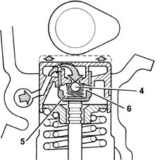
PHASE TRANSFORMER
Specifications
The "continuous" phase transformer is capable of modifying the position of the camshaft in relation to the crankshaft.In this way the engine is working with optimum timing in all operating points.The phase transformer is managed entirely by the engine management control unit which:- detects the camshaft position via the timing sensor;- alters this position according to the engine operation on the basis of a calibrated map;- keeps the camshaft position under control.