199000945 - 2110B34 MANUAL GEARBOX (6 SPEED) WITH DIFFERENTIAL - DISMANTLING AND REASSEMBLY - WASH, CHECK COMPONENTS, REPLACE SYNCHRONIZERS AND INTERNAL CONTROLS


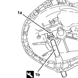
| The simultaneous engagement of two gears results in the gearbox shafts locking; this operation is necessary in order to be able to release the bolt and the nut securing the gears. |

| The nut must be replaced whenever it requires removal. |

| Tool | Description | Function | Validity |
|---|---|---|---|
| 1870481000 | Extractor | Layshaft bearing removal | 1.4 16v |


| To remove the circlips, arrange them with their openings at the front. |


| Tool | Description | Function | Validity |
|---|---|---|---|
| 1870899400 | Half plates | Removing layshaft bearings - gears - hubs - synchronizer rings | 1.4 16v |

| Tool | Description | Function | Validity |
|---|---|---|---|
| 1870899400 | Half plates | Removing layshaft bearings - gears - hubs - synchronizer rings | 1.4 16v |


| Tool | Description | Function | Validity |
|---|---|---|---|
| 1870899400 | Half plates | Removing layshaft bearings - gears - hubs - synchronizer rings | 1.4 16v |


| Tool | Description | Function | Validity |
|---|---|---|---|
| 1870899400 | Half plates | Removing layshaft bearings - gears - hubs - synchronizer rings | 1.4 16v |


| Tool | Description | Function | Validity |
|---|---|---|---|
| 1875088000 | Fitting tool | Fitting main shaft front bearing | 1.2 8v1.4 8v1.4 16v |

| Tool | Description | Function | Validity |
|---|---|---|---|
| 1870899300 | Fitting tool | Fitting 3rd-4th speed sliding sleeve hub/main shaft-layshaft rear bearingFitting spacer between 3rd-4th driven gears and 4th speed driven gear | 1.4 16v |


| The sliding sleeve should be fitted with the groove shown in the diagram facing downwards. |
| The notches on the sliding sleeve should be aligned with the pre-synchronizer mountings. |


| Tool | Description | Function | Validity |
|---|---|---|---|
| 1870899300 | Fitting tool | Fitting 3rd-4th speed sliding sleeve hub/main shaft-layshaft rear bearingFitting spacer between 3rd-4th driven gears and 4th speed driven gear | 1.4 16v |
| The rear bearing should be fitted with the groove "a" shown in the diagram facing upwards. |

| Tool | Description | Function | Validity |
|---|---|---|---|
| 2000007900 | Plate for bearing | Fitting layshaft front bearing | 1.4 16v |


| Tool | Description | Function | Validity |
|---|---|---|---|
| 1870632000 | Fitting tool | Fitting layshaft bearings - hubs - gears | 1.2 8v1.4 8v1.4 16v |


| The notches on the sleeve should be aligned with the pre-synchronizer mountings. |


| Tool | Description | Function | Validity |
|---|---|---|---|
| 1870632000 | Fitting tool | Fitting layshaft bearings - hubs - gears | 1.2 8v1.4 8v1.4 16v |

| Tool | Description | Function | Validity |
|---|---|---|---|
| 1870899300 | Fitting tool | Fitting 3rd-4th speed sliding sleeve hub/main shaft-layshaft rear bearingFitting spacer between 3rd-4th driven gears and 4th speed driven gear | 1.4 16v |

| Tool | Description | Function | Validity |
|---|---|---|---|
| 1870899300 | Fitting tool | Fitting 3rd-4th speed sliding sleeve hub/main shaft-layshaft rear bearingFitting spacer between 3rd-4th driven gears and 4th speed driven gear | 1.4 16v |

| Tool | Description | Function | Validity |
|---|---|---|---|
| 1870796000 | Fitting tool | Fitting oil seal on bellhousing | 1.4 16v |
| Tool | Description | Function | Validity |
|---|---|---|---|
| 1870007000 | Grip | Fitting differential mount bearing outer racesFitting main shaft oil seal on gearbox to engine mountFitting oil seal on differential coverFitting bearing on differential | 1.3 Multijet 75 CV1.3 Multijet 90 CV 5 speed1.2 8v1.4 8v1.4 16v1.9 Multijet1.3 Multijet 90 CV 6 speed1.4 16v TJet |


| Component | Fastening | dia | Value (daNm) | Validity |
|---|---|---|---|---|
| 5th speed engagement fork control pawl | Bolt | M6 | 1.1 ÷ 1.3 | 1.2 8v1.4 8v1.4 16v |

| Component | Fastening | dia | Value (daNm) | Validity |
|---|---|---|---|---|
| Support with fork lever for reverse gear engagement | Bolt | M8 | 1.4 ÷ 1.6 | 1.2 8v1.4 8v1.4 16v |

| Tool | Description | Function | Validity |
|---|---|---|---|
| 1870381000 | Fitting tool | Fitting gear cover rear bearing | 1.4 16v |
| Tool | Description | Function | Validity |
|---|---|---|---|
| 1860945000 | Fitting tool | Fitting 4th speed drive gear bush/main shaft rear bearing/1st and 2nd speed sliding sleeve hubFitting bearing | 1.4 16v1.3 Multijet 75 CV1.3 Multijet 90 CV 5 speed1.9 Multijet1.3 Multijet 90 CV 6 speed1.4 16v TJet |

| Component | Fastening | dia | Value (daNm) | Validity |
|---|---|---|---|---|
| Gearbox casing | Bolt | M8 | 1.8 ÷ 2.2 | 1.2 8v1.4 8v1.4 16v |
| Component | Fastening | dia | Value (daNm) | Validity |
|---|---|---|---|---|
| Manual gearbox reverse gear idler | Bolt | M8 | 2.3 ÷ 2.8 | 1.2 8v1.4 8v1.4 16v |

| Position the circlips with their openings at the front to facilitate fitting. |
| Component | Fastening | dia | Value (daNm) | Validity |
|---|---|---|---|---|
| Main and layshaft rear bearings retaining plate | Bolt | M8 | 1.8 ÷ 2.2 | 1.2 8v1.4 8v1.4 16v |

| Tool | Description | Function | Validity |
|---|---|---|---|
| 1870631000 | Fitting tool | Fitting rear bearing on main shaftFitting 4th and 5th speed driven gearsFitting 5th speed drive gear bushFitting hub for 5th speed engagement sliding sleeve | 1.2 8v1.4 8v1.4 16v |
| Tool | Description | Function | Validity |
|---|---|---|---|
| 1870631000 | Fitting tool | Fitting rear bearing on main shaftFitting 4th and 5th speed driven gearsFitting 5th speed drive gear bushFitting hub for 5th speed engagement sliding sleeve | 1.2 8v1.4 8v1.4 16v |
| The notches on the sleeve should be aligned with the pre-synchronizer mountings. |
| Tool | Description | Function | Validity |
|---|---|---|---|
| 1870631000 | Fitting tool | Fitting rear bearing on main shaftFitting 4th and 5th speed driven gearsFitting 5th speed drive gear bushFitting hub for 5th speed engagement sliding sleeve | 1.2 8v1.4 8v1.4 16v |
| Tool | Description | Function | Validity |
|---|---|---|---|
| 1870631000 | Fitting tool | Fitting rear bearing on main shaftFitting 4th and 5th speed driven gearsFitting 5th speed drive gear bushFitting hub for 5th speed engagement sliding sleeve | 1.2 8v1.4 8v1.4 16v |

| The simultaneous engagement of two gears results in the gearbox shafts locking; this operation is necessary in order to be able to lock the bolt and the nut securing the gears. |
| Component | Fastening | dia | Value (daNm) | Validity |
|---|---|---|---|---|
| Layshaft gears | Bolt (left hand thread) | M12 | 10.0 ÷ 11.0 | 1.4 16v |
| Component | Fastening | dia | Value (daNm) | Validity |
|---|---|---|---|---|
| Main shaft gears | Nut | M16 | 10.4 ÷ 12.6 | 1.4 16v |
| Tool | Description | Function | Validity |
|---|---|---|---|
| 1874140005 | Pair of heads | Staking ring nuts securing main and layshaft 5th speed | 1.2 8v1.4 8v1.4 16v |
| Tool | Description | Function | Validity |
|---|---|---|---|
| 1874140001 | Calliper | Staking ring nuts securing main and layshaft 5th speed | 1.2 8v1.4 8v1.4 16v |
| Component | Fastening | dia | Value (daNm) | Validity |
|---|---|---|---|---|
| Rear cover | Bolt | M6 | 0.5 | 1.2 8v1.4 8v1.4 16v |
| Component | Fastening | dia | Value (daNm) | Validity |
|---|---|---|---|---|
| Manual gearbox casing differential support | Bolt | M8 | 2.0 | 1.2 8v1.4 8v1.4 16v |
| Component | Fastening | dia | Value (daNm) | Validity |
|---|---|---|---|---|
| Manual gearbox casing differential support | Bolt | M10 | 3.5 | 1.2 8v1.4 8v1.4 16v |
| Tool | Description | Function | Validity |
|---|---|---|---|
| 1895655000 | Mount | Determining thickness of differential bearing scraper rings | 1.3 Multijet 75 CV1.3 Multijet 90 CV 5 speed1.2 8v1.4 8v1.4 16v1.4 16v TJet |

| Tool | Description | Function | Validity |
|---|---|---|---|
| 1895655000 | Mount | Determining thickness of differential bearing scraper rings | 1.3 Multijet 75 CV1.3 Multijet 90 CV 5 speed1.2 8v1.4 8v1.4 16v1.4 16v TJet |

| 0.12 mm corresponds to the recommended interference for the bedding in and pre-loading of the differential bearings. |
| Tool | Description | Function | Validity |
|---|---|---|---|
| 1870629000 | Fitting tool | Fitting oil seal on differential cover | 1.2 8v1.4 8v1.4 16v |
| Tool | Description | Function | Validity |
|---|---|---|---|
| 1870007000 | Grip | Fitting differential mount bearing outer racesFitting main shaft oil seal on gearbox to engine mountFitting oil seal on differential coverFitting bearing on differential | 1.3 Multijet 75 CV1.3 Multijet 90 CV 5 speed1.2 8v1.4 8v1.4 16v1.9 Multijet1.3 Multijet 90 CV 6 speed1.4 16v TJet |

| Component | Fastening | dia | Value (daNm) | Validity |
|---|---|---|---|---|
| Left flange on differential | Bolt | M8 | 2.0 | 1.2 8v1.4 8v1.4 16v |
| Tool | Description | Function | Validity |
|---|---|---|---|
| 1870629000 | Fitting tool | Fitting oil seal on differential cover | 1.2 8v1.4 8v1.4 16v |
| Tool | Description | Function | Validity |
|---|---|---|---|
| 1870007000 | Grip | Fitting differential mount bearing outer racesFitting main shaft oil seal on gearbox to engine mountFitting oil seal on differential coverFitting bearing on differential | 1.3 Multijet 75 CV1.3 Multijet 90 CV 5 speed1.2 8v1.4 8v1.4 16v1.9 Multijet1.3 Multijet 90 CV 6 speed1.4 16v TJet |

| Component | Fastening | dia | Value (daNm) | Validity |
|---|---|---|---|---|
| Manual gearbox gear engagement unit cover | Bolt | M6 | 2.0 | 1.2 8v1.4 8v1.4 16v |
| Tool | Description | Function | Validity |
|---|---|---|---|
| 1870633000 | Fitting tool | Fitting clutch thrust bearing control linkage inner bush | 1.2 8v1.4 8v1.4 16v |