199000425 - 1016E10 SINGLE CYLINDER HEAD, REMOVED - OVERHAUL
| Tool | Description | Function | Validity |
|---|---|---|---|
| 1860470000 | Mount | Head overhaul | 1.2 8v1.4 8v1.4 16v1.3 Multijet1.9 Multijet |
| Tool | Description | Function | Validity |
|---|---|---|---|
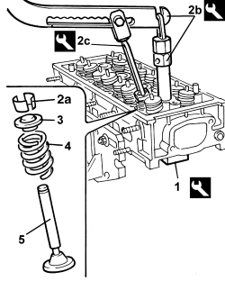
| 1860786000 | Base | Valve retention | 1.4 16v |
| Tool | Description | Function | Validity |
|---|---|---|---|
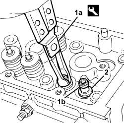
| 1860644000 | Lever | Dismantling valves | 1.4 16v |
| Tool | Description | Function | Validity |
|---|---|---|---|
| 1870890000 | Chamber | Dismantling valves | 1.4 16v |
| Tool | Description | Function | Validity |
|---|---|---|---|
| 1870894000 | Extractor | Valve guide oil seal extraction | 1.4 16v1.9 Multijet |
| Measurement | Value | Validity |
|---|---|---|
| Cylinder head support surface flatness (mm) | < 0.1 | 1.2 8v1.4 8v1.4 16v1.9 Multijet |
| Measurement | Value | Validity |
|---|---|---|
| Cylinder head height (factory value) (mm) | 77 | 1.4 16v TJet |
| Measurement | Value | Validity |
|---|---|---|
| Combustion chamber volume (cc) | 14.30 | 1.4 16v TJet |
| Measurement | Value | Validity |
|---|---|---|
| Inlet valve stem diameter (mm) | 5.982 ÷ 6.000 | 1.4 16v |
| Measurement | Value | Validity |
|---|---|---|
| Exhaust valve stem diameter (mm) | 5.974 ÷ 5.992 | 1.4 16v |
| Measurement | Value | Validity |
|---|---|---|
| Intake valve outer diameter (mm) | 26.75 ÷ 27.05 | 1.4 16v TJet |
| Measurement | Value | Validity |
|---|---|---|
| Exhaust valve outer diameter (mm) | 22.25 ÷ 22.55 | 1.4 16v TJet |
| Measurement | Value | Validity |
|---|---|---|
| Valve guide inner diameter (mm) | 6.022 ÷ 6.040 | 1.4 16v |
| Measurement | Value | Validity |
|---|---|---|
| Inlet valve/valve guide clearance (mm) | 0.022 ÷ 0.058 | 1.2 8v1.4 8v1.4 16v |
| Measurement | Value | Validity |
|---|---|---|
| Exhaust valve/valve guide clearance (mm) | 0.030 ÷ 0.066 | 1.2 8v1.4 8v1.4 16v |
| Measurement | Value | Validity |
|---|---|---|
| Valve spring height released (mm) | 46.9 | 1.4 16v |
| Measurement | Value | Validity |
|---|---|---|
| Height of valve springs under a load of 14.9 - 16.5 daN (mm) | 37.52 | 1.4 16v |
| Measurement | Value | Validity |
|---|---|---|
| Height of valve springs under a load of 31.1 - 34.1 daN (mm) | 30.0 | 1.4 16v |
| Tool | Description | Function | Validity |
|---|---|---|---|
| 1860993000 | Installing tool | Fitting valve guide oil sealing ring | 1.4 16v |
| Component | Fastening | dia | Value (daNm) | Validity |
|---|---|---|---|---|
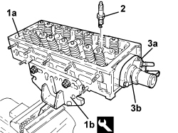
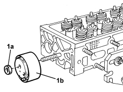
| Thermostat | Bolt | M6 | 0.9 ÷ 1.1 | 1.4 16v |
| Component | Fastening | dia | Value (daNm) | Validity |
|---|---|---|---|---|
| Spark plugs | - | M12 | 1.6 ÷ 2.0 | 1.4 16v |