199002753 - 4410D15 FRONT SUSPENSION CROSSMEMBER COMPLETE WITH TRACK CONTROL ARMS AND ANTI-ROLL BAR - R.R

| Tool | Description | Function | Validity |
|---|---|---|---|
| 1871000700 | Extractor | Extracting steering rod from strut |

| Tool | Description | Function | Validity |
|---|---|---|---|
| 2000001700 | Mount | Suspension crossmember support |
| Tool | Description | Function | Validity |
|---|---|---|---|
| 1870835001 | Column lift | Suspension crossmember support |
| Tool | Description | Function | Validity |
|---|---|---|---|
| 2000007600 | Chassis | Suspension crossmember support |
| Tool | Description | Function | Validity |
|---|---|---|---|
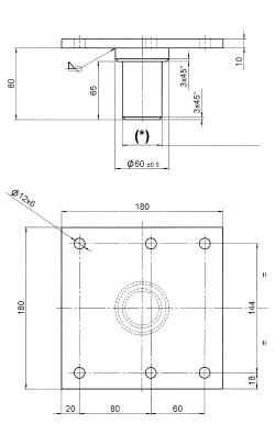
| 2000007700 | Adaptors | Front suspension crossmember support |
| The adapators (2b) supplied are burnished black with M12 threads for fitting on the frame. |

| Component | Fastening | dia | Value (daNm) | Validity |
|---|---|---|---|---|
| Front suspension crossmember to body | Bolt | M12 | 12.1 ÷ 14.8 |
| Component | Fastening | dia | Value (daNm) | Validity |
|---|---|---|---|---|
| Anti-roll bar joint | Nut | M10 | 4.5 ÷ 5.5 |
| Component | Fastening | dia | Value (daNm) | Validity |
|---|---|---|---|---|
| Steering rod to pillar | Nut | M10 | 3.6 ÷ 4.4 |
| Component | Fastening | dia | Value (daNm) | Validity |
|---|---|---|---|---|
| Front suspension lower wishbone - strut side | Bolt | M10 | 5.4 ÷ 6.6 |
| Component | Fastening | dia | Value (daNm) | Validity |
|---|---|---|---|---|
| Steering column to steering box pinion | Bolt | M10 | 5.0 ÷ 6.0 |