2584167 - 1016C10 cylinder head - r + r and replace gasket
| Collect the coolant that comes out in a suitable container. |


| The front hose must be protected against any mechanical damage from outside. It should not come into contact with corrosive products; the front flexible pipe cannot withstand any distortion when it is in position. |
| Failure to follow these precautions will result in the shortening of the life of the flexible pipe; separation or dismantling the exhaust line is compulsory for operations that require the power unit to be raised. |

| Description | Code | |
|---|---|---|
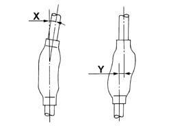
| 1 | Dial gauge support | 1.870.404.001 |

| Measurement | Value | ||
|---|---|---|---|
| - | Cylinder head gasket size (no hole) (mm) | 0.67 ÷ 0.77 | |
| Average - maximum piston projection (mm) | 0.028 ÷ 0.127 | ||
| Measurement | Value | ||
|---|---|---|---|
| - | Cylinder head gasket size (no hole) (mm) | 0.77 ÷ 0.87 | |
| Average - maximum piston projection (mm) | 0.128 ÷ 0.227 | ||
| Measurement | Value | ||
|---|---|---|---|
| - | Cylinder head gasket size (no hole) (mm) | 0.87 ÷ 0.97 | |
| Average - maximum piston projection (mm) | 0.228 ÷ 0.327 | ||
| Apply a thin layer of sealant to the timing cover gasket so that it is not too thick and avoid excess sealant inside the timing cover. |

| Before moving the cylinder head, apply grease to the belt tensioner piston to prevent it emerging accidentally during moving. |
| During this stage, do not tighten the bolt into hole (a). |
| Fastening | Component | dia | Value(daNm) | |
|---|---|---|---|---|
| 1 | Bolt | TIMING COVER | M6 | 0.8 ÷ 1.0 |
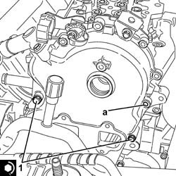
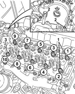
| Follow the order shown in the figure for each tightening sequence. |
| Fastening | Component | dia | Value(daNm) | |
|---|---|---|---|---|
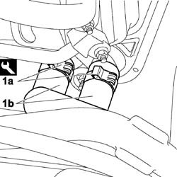
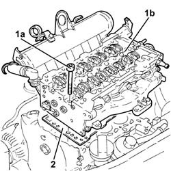
| 1a | Bolt | CYLINDER HEAD | M10 | (Engine crankcase side) 3.8 - 4.2 +90 + 90? |
| Description | Code | |
|---|---|---|
| 1b | Torque wrench | 1.860.942.000 |

| Fastening | Component | dia | Value(daNm) | |
|---|---|---|---|---|
| 1 | Bolt | TIMING COVER | M6 | 0.8 ÷ 1.0 |

| It is only possible for the cylinder head to protrude from the crankcase. |
| Measurement | Value | ||
|---|---|---|---|
| - | Cylinder head - crankcase misalignment (mm) | 0.1 |
| Fastening | Component | dia | Value(daNm) | |
|---|---|---|---|---|
| 1 | Bolt | OIL RETURN PIPE FROM TURBO | M6 | (Turbocharger/ngine crankcase side) 0.8 - 1.0 |

| Fastening | Component | dia | Value(daNm) | |
|---|---|---|---|---|
| 1 | Nut | TURBOCHARGER | M8 | (Exhaust manifold side) 2.3 - 2.8 |
| Replace the copper washers on the connectors. |
| Fastening | Component | dia | Value(daNm) | |
|---|---|---|---|---|
| - | Connector | OIL DELIVERY PIPE TO TURBO | M10 | (Turbocharger/oil filter mount side) 1.1 - 1.3 |