2585282 - 1004E20 engine - dismantle and re-build following operation 1004e10 - wash and check dismantled parts - re-fit cylinder head and oil sump - does not include repairs to cylinder head and auxiliary unit
| Remove the electrical components before washing to prevent damaging them through the chemical compounds used for washing. |


| Description | Code | |
|---|---|---|
| 2 | Blade | 1.870.718.000 |


| Measurement | Value | ||
|---|---|---|---|
| 1 | End float (mm) | 0.055 ÷ 0.265 |

| The central main bearing half is joined to the thrust half-rings. Press the ends of the half-bearing to separate. |


| Measurement | Value | ||
|---|---|---|---|
| 1 | Cylinder liner diameter (mm) | Category A | 69.600 ÷ 69.610 |
| Category B | 69.610 ÷ 69.620 | ||
| Category C | 69.620 ÷ 69.630 | ||
| Measurement | Value | ||
|---|---|---|---|
| - | Cylinder liner taper (mm) | < 0.010 |
| Measurement | Value | ||
|---|---|---|---|
| - | Cylinder liner ovality (mm) | ± 0.005 |
| In the case of reaming, all the bores must have the same oversize. |
| Measurement | Value | ||
|---|---|---|---|
| - | Cylinder liner oversize (mm) | 0.1 |

| Fastening | Component | dia | Value(daNm) | |
|---|---|---|---|---|
| 1a | Central bolt | ENGINE CRANKCASE | M10 | (Engine crankcase side) 1.9 - 2.1 + 80 ± 3? |
| Description | Code | |
|---|---|---|
| 1b | Torque wrench | 1.860.942.000 |
| Fastening | Component | dia | Value(daNm) | |
|---|---|---|---|---|
| 2 | Central bolt | ENGINE CRANKCASE | M8 | (Engine crankcase side) 2.9 - 3.2 |
| Measurement | Value | ||
|---|---|---|---|
| 3 | Main journal seat diameter (mm) | Category A | 54.710 ÷ 54.714 |
| Category B | 54.714 ÷ 54.718 | ||
| Category C | 54.718 ÷ 54.722 | ||

| Measurement | Value | ||
|---|---|---|---|
| - | Main journal diameter (mm) | Category A | 50.994 ÷ 51.000 |
| Category B | 50.988 ÷ 50.994 | ||
| Category C | 50.982 ÷ 50.988 | ||
| Measurement | Value | ||
|---|---|---|---|
| - | Main journal undersize (mm) | 0.127 |
| Crankpin undersizes higher than the value mentioned will adversely affect the structural resistance of the crankshaft (following contact between the tool and rolled connectors). As far as the above is concerned, if the regrinding requires undersizes greater than 0.127 mm, then the crankshaft must be replaced and a new one ordered from the Parts Dept. The half-bearings used for undersizes of more than 0.127 mm should not be ordered from the Parts Dept. (even if the number is still quoted). |
| Measurement | Value | ||
|---|---|---|---|
| - | Crankpin diameter (mm) | Category A | 42.591 ÷ 42.600 |
| Category B | 42.582 ÷ 42.591 | ||
| Measurement | Value | ||
|---|---|---|---|
| - | Crankpin undersize (mm) | 0.127 |
| Crankpin undersizes higher than the value mentioned will adversely affect the structural resistance of the crankshaft (following contact between the tool and rolled connectors). As far as the above is concerned, if the regrinding requires undersizes greater than 0.127 mm, then the crankshaft must be replaced and a new one ordered from the Parts Dept. The half-bearings used for undersizes of more than 0.127 mm should not be ordered from the Parts Dept. (even if the number is still quoted). |
| Measurement | Value | ||
|---|---|---|---|
| - | Main bearing half thickness (mm) | Category A | 1.836 ÷ 1.841 |
| Category B | 1.841 ÷ 1.846 | ||
| Category C | 1.846 ÷ 1.851 | ||
| Measurement | Value | ||
|---|---|---|---|
| - | Connecting rod half-bearing thickness (mm) | Category A | 1.546 ÷ 1.552 |
| Category B | 1.550 ÷ 1.556 | ||
| Half-bearings of different categories may be fitted to the same journal to reduce the clearance. In the above case, observe the following installation requirements. Fit the thickest half-bearing to the main bearing cap and the thinnest to the crankcase. |
| If the crankshaft has been ground, fit new oversize half-bearings to restore the initial tolerance conditions. The thrust half-rings are built into the central main bearing half. |
| Measurement | Value | ||
|---|---|---|---|
| - | Thrust half-washer thickness (mm) | 2.310 ÷ 2.360 |
| The thrust half-washer undersize is 0.127 mm. |

| Fastening | Component | dia | Value(daNm) | |
|---|---|---|---|---|
| 2a | Central bolt | ENGINE CRANKCASE | M10 | (Engine crankcase side) 1.9 - 2.1 + 80 ± 3? |
| Description | Code | |
|---|---|---|
| 2b | Torque wrench | 1.860.942.000 |
| Fastening | Component | dia | Value(daNm) | |
|---|---|---|---|---|
| 3 | Central bolt | ENGINE CRANKCASE | M8 | (Engine crankcase side) 2.9 - 3.2 |

| Check one journal at a time, without rotating the crankshaft. |
| Measurement | Value | ||
|---|---|---|---|
| 1b | Clearance between main bearings - crankshaft main journals (mm) | 0.028 ÷ 0.048 |
| If the figure measured is outside of the tolerance, replace the half-bearings with ones of the correct size and category. |

| The sealant strip must be unbroken. The sealant strip diameter must be 2.5 - 3.5 mm |
| Type | Component | Description | Qty. | |
|---|---|---|---|---|
| 1 | Silicon sealant | ENGINE CRANKCASE | Loctite 5900 | - |

| Measurement | Value | ||
|---|---|---|---|
| - | Inner diameter (mm) | 23.006 ÷ 23.012 |
| Measurement | Value | ||
|---|---|---|---|
| - | Piston pin housing diameter (mm) | 22.990 ÷ 22.996 |
| Measurement | Value | ||
|---|---|---|---|
| - | Outer diameter (mm) | 22.982 ÷ 22.987 |
| Measurement | Value | ||
|---|---|---|---|
| - | Gap (mm) | 1st sealing ring | 0.20 ÷ 0.30 |
| 2nd sealing ring | 1.0 ÷ 1.5 | ||
| Measurement | Value | ||
|---|---|---|---|
| - | Gap (mm) | Oil scaper ring | 0.25 - 0.50 |
| Measurement | Value | ||
|---|---|---|---|
| - | Outer diameter (mm) | Category A | 69.520 ÷ 69.530 |
| Category B | 69.530 ÷ 69.540 | ||
| Category C | 69.540 ÷ 69.550 | ||
| Measure perpendicular to the gudgeon pin axis, 12 mm from the lower edge of the skirt. |
| Measurement | Value | ||
|---|---|---|---|
| - | Backlash, first ring (mm) | 0.09 ÷ 0.13 |
| Measurement | Value | ||
|---|---|---|---|
| 1a | Backlash, 2nd ring (mm) | 0.04 ÷ 0.08 |
| Measurement | Value | ||
|---|---|---|---|
| - | End float (mm) | 0.030 ÷ 0.070 |

| The connecting rods are pre-set fracture type and are supplied already fractured by Parts together with the cap bolts. The connecting rod caps are not interchangeable because the fracture profile differs from part to part. |
| Fastening | Component | dia | Value(daNm) | |
|---|---|---|---|---|
| 1c | Bolt | CONNECTING ROD CAPS | M8 | 1.9 ÷ 2.1 + 40? ± 2? |
| Description | Code | |
|---|---|---|
| - | Torque wrench | 1.860.942.000 |
| Measurement | Value | ||
|---|---|---|---|
| 2 | Big end diameter (mm) | 45.734 ÷ 45.744 |

| The engine oil spray bolts are pretreated with locking compound and should be replaced whenever they are refitted. |
| Fastening | Component | dia | Value(daNm) | |
|---|---|---|---|---|
| - | Bolt | PISTON COOLING NOZZLES | M6 | (Engine crankcase side) 0.8 - 1.0 |
| Description | Code | |
|---|---|---|
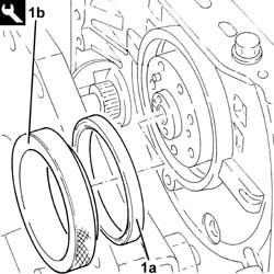
| 1 | Flange | 1.860.815.000 |


| The connecting rod bearing halves may be identified as follows:upper connecting rod bearing half, connecting rod side, trimetallic and dark in colour;lower connecting rod bearing half, cap side bimetallic, light coloured with a hole.Never reverse the positioning of the connecting rod bearing halves under any circumstances. |


| The connecting rod bearing halves may be identified as follows:upper connecting rod bearing half, connecting rod side, trimetallic and dark in colour;lower connecting rod bearing half, cap side bimetallic, light coloured with a hole.Never reverse the positioning of the connecting rod bearing halves under any circumstances. |
| Fastening | Component | dia | Value(daNm) | |
|---|---|---|---|---|
| 2a | Bolt | CONNECTING ROD CAPS | M8 | 1.9 ÷ 2.1 + 40? ± 2? |
| Description | Code | |
|---|---|---|
| 2b | Torque wrench | 1.860.942.000 |

| Check one journal at a time, without rotating the crankshaft. |
| Measurement | Value | ||
|---|---|---|---|
| 1b | Crankshaft crankpins (mm) | 0.030 ÷ 0.062 |
| If the figure measured is outside of the tolerance, replace the connecting rod half-bearings with ones of the correct size and category. |

| Description | Code | |
|---|---|---|
| - | Flange | 1.860.815.000 |
| Description | Code | |
|---|---|---|
| 1b | Fitting tool | 1.870.900.200 |
| Fastening | Component | dia | Value(daNm) | |
|---|---|---|---|---|
| 1b | - | STARTER MOTOR | M8 | (Engine crankcase side) 2.3 - 2.8 |
| Fastening | Component | dia | Value(daNm) | |
|---|---|---|---|---|
| 2b | Bolt | ENGINE OIL RECOVERY MANIFOLD | M6 | (Engine crankcase side) 0.8 - 1.0 |

| Fastening | Component | dia | Value(daNm) | |
|---|---|---|---|---|
| 1b | Bolt | ALTERNATOR SUPPORT | M8 | (Engine crankcase side) 2.3 - 2.8 |

| Fastening | Component | dia | Value(daNm) | |
|---|---|---|---|---|
| 1b | Bolt | ALTERNATOR ASSEMBLY | M8 | (Mount side) 2.3 - 2.8 |

| Fastening | Component | dia | Value(daNm) | |
|---|---|---|---|---|
| 1b | Bolt | COMPRESSOR MOUNT (AC) | M8 | (Upper and lower engine crankcase side) 2.3 - 2.8 |

| Fastening | Component | dia | Value(daNm) | |
|---|---|---|---|---|
| 1b | Bolt | AIR CONDITIONER ASSEMBLY COMPRESSOR | M8 | (Mount side) 2.3 - 2.8 |
| Ensure the gasket is present, undamaged and correctly positioned. |
| Fastening | Component | dia | Value(daNm) | |
|---|---|---|---|---|
| 2d | Bolt | OIL FILTER MOUNT | M6 | (Engine crankcase side) 0.8 - 1.0 |

| Fit the rigid pipe in the crankcase very carefuly to ensure the o-ring is correctly positioned. |
| Fastening | Component | dia | Value(daNm) | |
|---|---|---|---|---|
| 2b | Bolt | ENGINE RPM AND TIMING SENSOR | M6 | (Engine crankcase side) 0.8 - 1.0 |

| Description | Code | |
|---|---|---|
| 1 | Dial gauge support | 1.870.404.001 |

| Measurement | Value | ||
|---|---|---|---|
| - | Cylinder head gasket size (no hole) (mm) | 0.67 ÷ 0.77 | |
| Average - maximum piston projection (mm) | 0.028 ÷ 0.127 | ||
| Measurement | Value | ||
|---|---|---|---|
| - | Cylinder head gasket size (one hole) (mm) | 0.77 ÷ 0.87 | |
| Average - maximum piston projection (mm) | 0.128 ÷ 0.227 | ||
| Measurement | Value | ||
|---|---|---|---|
| - | Cylinder head gasket size (two holes) (mm) | 0.87 ÷ 0.97 | |
| Average - maximum piston projection (mm) | 0.228 ÷ 0.327 | ||

| Description | Code | |
|---|---|---|
| 1 | Template | 1.870.900.300 |

| Follow the order shown in the figure for each tightening sequence. The nominal tightening of 4.0 daNm is performed in two stages: a pretightening to 2.0 daNm followed by an additional tightening of 2.0 daNm. |
| Fastening | Component | dia | Value(daNm) | |
|---|---|---|---|---|
| 4 | Bolt | CYLINDER HEAD | M10 | (Engine crankcase side) 3.8 - 4.2 +90 + 90? |
| Description | Code | |
|---|---|---|
| 4 | Torque wrench | 1.860.942.000 |

| It is only possible for the cylinder head to protrude from the crankcase. |
| Measurement | Value | ||
|---|---|---|---|
| - | Cylinder head - crankcase misalignment (mm) | 0.1 |

| Fit the tools and position with their millings horizontal. Ensure they fit into the seats on the camshafts. |
| Description | Code | |
|---|---|---|
| 1b | Templates | 1.870.896.900 |


| Follow the order shown in the figure for each tightening sequence. |
| Fastening | Component | dia | Value(daNm) | |
|---|---|---|---|---|
| 2a | Bolt | CYLINDER HEAD EXTENSION | M8 | (Lower cylinder head side) 2.5 |
| Fastening | Component | dia | Value(daNm) | |
|---|---|---|---|---|
| 2b | Bolt | CYLINDER HEAD EXTENSION | M7 | (Lower cylinder head side) 1.8 |

| It is only possible for the cylinder head extension to protrude from the cylinder head. |
| Measurement | Value | ||
|---|---|---|---|
| - | Misalignment between cylinder head extension - cylinder head (mm) | 0.1 |

| Before refitting, replace the copper ring on the injectors. |
| Fastening | Component | dia | Value(daNm) | |
|---|---|---|---|---|
| 3 | Nut | INJECTORS(DIESEL) | M8 | (Cylinder head side) 1.8 - 2.2 |

| Fastening | Component | dia | Value(daNm) | |
|---|---|---|---|---|
| 1b | Bolt | MOBILE TIMING TENSIONER | M6 | (Cylinder head side) 0.8 - 1.0 |

| Fit the exhaust side camshaft toothed drive pulley and the toothed drive pulley according to the position marked on disassembly. If the pulleys are replaced, fit with the wording facing outwards. |

| Fastening | Component | dia | Value(daNm) | |
|---|---|---|---|---|
| 1 | Bolt | TIMING DRIVEN PULLEY | M12 | (Exhaust camshaft side) 10.8 - 13.2 |

| Fastening | Component | dia | Value(daNm) | |
|---|---|---|---|---|
| 4 | Connector | PIPE FUEL MANIFOLD TO INJECTORS | M12 | (Injector side) 2.3 - 2.5 |
| Fastening | Component | dia | Value(daNm) | |
|---|---|---|---|---|
| 5 | Connector | PIPE FUEL MANIFOLD TO INJECTORS | M14 | (Fuel manifold side) 2.7 - 2.9 |
| Clean the threaded pipe seats on the manifold and injectors with heptane. |
| Fastening | Component | dia | Value(daNm) | |
|---|---|---|---|---|
| 7 | Connector | PRESSURE PUMP LINE TO FUEL MANIFOLD | M12 | (Pressure pump side) 2.3 - 2.5 |
| Fastening | Component | dia | Value(daNm) | |
|---|---|---|---|---|
| 8 | Connector | PRESSURE PUMP LINE TO FUEL MANIFOLD | M14 | (Fuel manifold side) 2.7 - 2.9 |

| Description | Code | |
|---|---|---|
| 1 | Hose | 1.870.900.600 |
| Fastening | Component | dia | Value(daNm) | |
|---|---|---|---|---|
| 2c | Bolt | FRONT COVER CRANKSHAFT | M6 | 0.8 ÷ 1.0 |

| Ensure the o-ring is present and correctly positioned. |
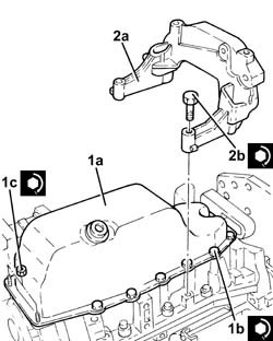
| The sealant strip must be unbroken. The sealant strip diameter must be 3.5 0.5 mm |
| Type | Component | Description | Qty. | |
|---|---|---|---|---|
| - | Sealant | ENGINE OIL SUMP | LOCTITE 5900 | - |

| Fastening | Component | dia | Value(daNm) | |
|---|---|---|---|---|
| 1b | Bolt | ENGINE OIL SUMP | M6 | (Lower engine crankcase side) 0.8 - 1.0 |
| Fastening | Component | dia | Value(daNm) | |
|---|---|---|---|---|
| 1c | Nut | ENGINE OIL SUMP | M6 | (Cam cover side) 0.8 ÷ 1.0 |
| Fastening | Component | dia | Value(daNm) | |
|---|---|---|---|---|
| 2b | Bolt | GEARBOX/ENGINE COUPLING BRACKET | M8 | (Lower engine crankcase side) 2.7 - 3.3 |
| Fastening | Component | dia | Value(daNm) | |
|---|---|---|---|---|
| - | Bolt | FRONT DRIVE SHAFT BEARING MOUNT | M8 | (Lower engine crankcase side) 2.0 - 2.4 |
| Description | Code | |
|---|---|---|
| - | Hose | 1.870.900.600 |

| Fastening | Component | dia | Value(daNm) | |
|---|---|---|---|---|
| 1b | Nut | COOLANT PUMP | M6 | (Engine upper crankcase side) 0.8 - 1.0 |
| Fastening | Component | dia | Value(daNm) | |
|---|---|---|---|---|
| 3b | Bolt | SINGLE BELT MOVING TENSIONER VARIOUS | M10 | (Engine upper crankcase side) 4.5 - 5.5 |

| Fastening | Component | dia | Value(daNm) | |
|---|---|---|---|---|
| 1c | Bolt | RIGID ENGINE MOUNT, TIMING SIDE | M10 | (Engine upper crankcase side) 5.7 - 6.3 |

| Fastening | Component | dia | Value(daNm) | |
|---|---|---|---|---|
| 1c | Nut | TURBOCHARGER | M8 | (Exhaust manifold side) 2.3 - 2.8 |

| Fold over the gasket safety tabs. |
| Replace the copper washers on the connectors. |
| Fastening | Component | dia | Value(daNm) | |
|---|---|---|---|---|
| 1b | Connector | OIL DELIVERY PIPE TO TURBO | M10 | (Turbocharger/oil filter mount side) 1.1 - 1.3 |
| Fastening | Component | dia | Value(daNm) | |
|---|---|---|---|---|
| 2 | Bolt | OIL RETURN PIPE FROM TURBO | M6 | (Turbocharger/ngine crankcase side) 0.8 - 1.0 |
