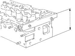
2585285 - 1016E10 single cylinder head, removed - overhaul
| Description | Code | |
|---|---|---|
| 1b | Support | 1.860.470.001 |


| Description | Code | |
|---|---|---|
| - | Templates | 1.870.896.900 |
| Measurement | Value | ||
|---|---|---|---|
| - | End float (mm) | 0.15 ÷ 0.34 |
| Fit the tool and position with its millings horizontal. Ensure it fits nto the seat on the camshaft. |
| Description | Code | |
|---|---|---|
| 1b | Templates | 1.870.896.900 |

| Description | Code | |
|---|---|---|
| 1 | Templates | 1.870.896.900 |


| Description | Code | |
|---|---|---|
| 1b | Support | 1.860.470.001 |


| Description | Code | |
|---|---|---|
| 1 | Stand | 1.860.749.000 |

| Description | Code | |
|---|---|---|
| 1b | Lever | 1.860.644.001 |
| Description | Code | |
|---|---|---|
| 1c | Chamber | 1.870.881.000 |

| Description | Code | |
|---|---|---|
| - | Stand | 1.860.749.000 |
| Description | Code | |
|---|---|---|
| 1b | Caliper | 1.870.894.000 |

| Description | Code | |
|---|---|---|
| - | Support | 1.860.470.000 |
| Measurement | Value | ||
|---|---|---|---|
| - | Lower plane planarity (mm) | 0.1 |
| When within limit conditions (head gasket with 2 notches before levelling), the lower head surface cannot be levelled. |
| Measurement | Value | ||
|---|---|---|---|
| - | Nominal height (mm) | 105.5 ± 0.05 |
| Measurement | Value | ||
|---|---|---|---|
| - | Intake/exhaust stem diameter (mm) | 5.90 ÷ 5.94 |
| Measurement | Value | ||
|---|---|---|---|
| - | Free length (mm) | 37.9 |
| Measurement | Value | ||
|---|---|---|---|
| - | Length (mm) | 31.0 | |
| Under a load of (daN) | 16.2 ÷ 18.0 | ||
| Measurement | Value | ||
|---|---|---|---|
| - | Length (mm) | 23.5 | |
| Under a load of (daN) | 36.1 ÷ 39.5 | ||
| Measurement | Value | ||
|---|---|---|---|
| - | Journal diameter (mm) | First journal | 38.500 ÷ 38.515 |
| Second journal | 38.000 ÷ 38.015 | ||
| Third journal | 30.000 ÷ 30.015 | ||
| Measurement | Value | ||
|---|---|---|---|
| - | Nominal cam height (mm) | Inlet | 6.4 |
| Exhaust | 7.5 | ||
| Measurement | Value | ||
|---|---|---|---|
| 1 | Bearing diameter (mm) | First bearing | 38.545 ÷ 38.570 |
| Second bearing | 38.045 ÷ 38.070 | ||
| Third bearing | 30.045 ÷ 30.070 | ||

| Measurement | Value | ||
|---|---|---|---|
| 1 | Angle of ring in contact with valve (-) | 45° ± 20'' |

| Description | Code | |
|---|---|---|
| - | Support | 1.860.470.001 |
| Description | Code | |
|---|---|---|
| - | Stand | 1.860.749.000 |
| Description | Code | |
|---|---|---|
| 1b | Drift | 1.870.900.800 |

| Description | Code | |
|---|---|---|
| 3b | Lever | 1.860.644.001 |
| Description | Code | |
|---|---|---|
| 3c | Chamber | 1.870.881.000 |

| Description | Code | |
|---|---|---|
| - | Stand | 1.860.749.000 |
| Fastening | Component | dia | Value(daNm) | |
|---|---|---|---|---|
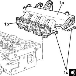
| 1c | Bolt | INLET AIR DUCT | M8 | (Cylinder head side) 2.3 - 2.8 |
| Fastening | Component | dia | Value(daNm) | |
|---|---|---|---|---|
| 1d | Bolt | EGR EXHAUST GAS HEAT EXCHANGER | M8 | (Cylinder head side) 2.0 - 2.4 |

| Fastening | Component | dia | Value(daNm) | |
|---|---|---|---|---|
| 1 | - | INSUFFICIENT ENGINE OIL PRESSURE SWITCH | M14 | (Cylinder head side) 2.9 - 3.5 |
| Fastening | Component | dia | Value(daNm) | |
|---|---|---|---|---|
| 2b | Bolt | THERMOSTAT | M8 | (Cylinder head side) 2.3 - 2.8 |

| Position the hydraulic tappets with the oil channel hole turned toward the outside of the cylinder head: this position brings the hole into communication with the oil duct on the lower cylinder head. |
| Description | Code | |
|---|---|---|
| - | Support | 1.860.470.001 |
| Fastening | Component | dia | Value(daNm) | |
|---|---|---|---|---|
| 1 | - | GLOW PLUGS | M8 | (Cylinder head side) 0.9 - 1.0 |
| Fastening | Component | dia | Value(daNm) | |
|---|---|---|---|---|
| 3b | Nut | EXHAUST MANIFOLD/S | M8 | (Cylinder head side) 2.1 - 2.5 |

| Description | Code | |
|---|---|---|
| - | Support | 1.860.470.001 |
| Fit the tools and position with their millings horizontal. Ensure they fit into the seats on the camshafts. |
| Description | Code | |
|---|---|---|
| 1 | Templates | 1.870.896.900 |
| Fastening | Component | dia | Value(daNm) | |
|---|---|---|---|---|
| 2 | Bolt | CYLINDER HEAD EXTENSION | M12 | (camshaft side) 10.8 - 13.2 |

| Fastening | Component | dia | Value(daNm) | |
|---|---|---|---|---|
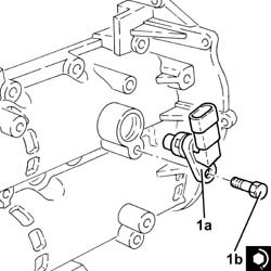
| 1b | Bolt | CAM ANGLE SENSOR | M6 | (Cylinder head extension side) 0.6 - 0.8 |
| Fastening | Component | dia | Value(daNm) | |
|---|---|---|---|---|
| 1c | Bolt | PRESSURE PUMP | M7 | (Cylinder head extension side) 1.4 - 1.7 |
| Follow the order shown in the figure for each tightening sequence. The tightening to 2.0 daNm is performed in two stages: a pretightening to 0.5 daNm followed by an additional tightening of 1.8 -2.2 daNm. |
| Fastening | Component | dia | Value(daNm) | |
|---|---|---|---|---|
| 2c | Bolt | VACUUM PUMP FOR BRAKES | M8 | (Cylinder head side) 1.8 - 2.2 |
