2585291 - 1028H14 piston connecting rod set - r r


| Description | Code | |
|---|---|---|
| 1 | Flange | 1.860.815.000 |

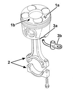
| The connecting rod bearing halves may be identified as follows:upper connecting rod bearing half, connecting rod side, trimetallic and dark in colour;lower connecting rod bearing half, cap side bimetallic, light coloured with a hole.Never reverse the positioning of the connecting rod bearing halves under any circumstances. |


| The connecting rod bearing halves may be identified as follows:upper connecting rod bearing half, connecting rod side, trimetallic and dark in colour;lower connecting rod bearing half, cap side bimetallic, light coloured with a hole.Never reverse the positioning of the connecting rod bearing halves under any circumstances. |
| Fastening | Component | dia | Value(daNm) | |
|---|---|---|---|---|
| 2a | Bolt | CONNECTING ROD CAPS | M8 | 1.9 ÷ 2.1 + 40? ± 2? |
| Description | Code | |
|---|---|---|
| 2b | Torque wrench | 1.860.942.000 |

| Check one journal at a time, without rotating the crankshaft. |
| Measurement | Value | ||
|---|---|---|---|
| 1b | Crankshaft crankpins (mm) | 0.030 ÷ 0.062 |
| If the figure measured is outside of the tolerance, replace the connecting rod half-bearings with ones of the correct size and category. |

| Description | Code | |
|---|---|---|
| - | Flange | 1.860.815.000 |
| Fastening | Component | dia | Value(daNm) | |
|---|---|---|---|---|
| 1b | Bolt | COMPRESSOR MOUNT (AC) | M8 | (Upper and lower engine crankcase side) 2.3 - 2.8 |

| Fastening | Component | dia | Value(daNm) | |
|---|---|---|---|---|
| 1b | Bolt | AIR CONDITIONER ASSEMBLY COMPRESSOR | M8 | (Mount side) 2.3 - 2.8 |
