2585314 - 2110B20 manual gearbox (5 speed) with differential - dismantle and rebuild - wash and check parts - replace synchronisers and internal controls if necessary
Release the gearbox and differential from the support tool used for the removal-refitting from the vehicle. | Name | Country |
|---|---|---|
| - | Gearbox mount | 1.860.873.000 |
| Two operators are needed for this operation. |
| Name | Country |
|---|---|---|
| 1b | Rotating stand | 1.871.000.000 |
| Name | Country |
|---|---|---|
| 1c | Support | 1.871.001.014 |


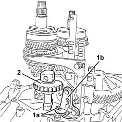
| The simultaneous enagement of two gears will result in the gearbox shafts locking. |
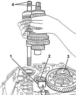
| Positioning the selector fork for 5th speed in neutral is necessary to prevent losing the synchronizer rollers. |


| take care not to damage the tapered part of the sleeve and the ends of the selector fork with the drift. |


| Name | Country |
|---|---|---|
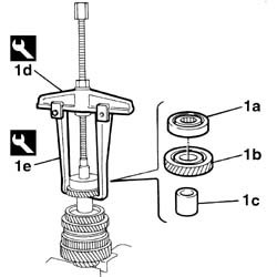
| 1d | Extractor | 1.840.005.002 |
| Name | Country |
|---|---|---|
| 1e | Clamps | 1.840.005.303 |
| Name | Country |
|---|---|---|
| 1c | Extractor | 1.840.005.002 |
| Name | Country |
|---|---|---|
| 1d | Clamps | 1.840.005.306 |


| When refitting, replace the circplip. |

| Name | Country |
|---|---|---|
| 1d | Extractor | 1.840.005.002 |
| Name | Country |
|---|---|---|
| 1e | Clamps | 1.840.005.306 |

| Name | Country |
|---|---|---|
| 1n | Extractor | 1.840.005.002 |
| Name | Country |
|---|---|---|
| 1o | Clamps | 1.840.005.306 |

| Name | Country |
|---|---|---|
| 1b | Fitting tool | 1.860.945.000 |

| Name | Country |
|---|---|---|
| 1b | Fitting tool | 1.860.945.000 |

| Name | Country |
|---|---|---|
| 1b | Fitting tool | 1.860.945.000 |


| Name | Country |
|---|---|---|
| 1b | Fitting tool | 1.870.465.000 |

| Name | Country |
|---|---|---|
| 2b | Fitting tool | 1.870.465.000 |

| Name | Country |
|---|---|---|
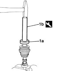
| 1b | Drift | 1.870.448.000 |

 | Fastening | Component | Ø | Value(daNm) |
|---|---|---|---|---|
| 1b | Bolt | GEAR ENGAGMENT SELECTOR LEVER | M8 | 1.5 |


| Make sure that the gear engagement teeth are facing downwards. |
| Position the safety pawl in the rod before fitting it in the housing. |
| To faciliate the fitting, move the 2nd-3rd control rods in the direction shown by the arrow. |
| Fastening | Component | Ø | Value(daNm) |
|---|---|---|---|---|
| 5a | Bolt | GEARBOX INTERNAL CONTROLS | M6 | 1.8 |
| Fastening | Component | Ø | Value(daNm) |
|---|---|---|---|---|
| 5b | Bolt | GEARBOX INTERNAL CONTROLS | M6 | 1.8 |
| Fastening | Component | Ø | Value(daNm) |
|---|---|---|---|---|
| 6b | Bolt | GEARBOX INTERNAL CONTROLS | M6 | 10 |

 | Type | Component | Name | Qty. |
|---|---|---|---|---|
| - | Sealant | GEARBOX SEALS/GASKETS | Loctite 573 | - |
| Keep the gear selector/engagement lever upwards and check that the gear selector engages in the 3rd-4th speed selector fork. |
| Fastening | Component | Ø | Value(daNm) |
|---|---|---|---|---|
| - | Bolt | GEARBOX GEAR CASING | M8 | 2.5 |
| Fastening | Component | Ø | Value(daNm) |
|---|---|---|---|---|
| - | Bolt | REVERSE IDLER | M7 | 3.4 |
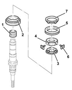
| To facilitate the fitting of the circlips, place them with their openings at the front. |
| Type | Component | Name | Qty. |
|---|---|---|---|---|
| - | Sealant | GEARBOX SEALS/GASKETS | Loctite 573 | - |
| Fastening | Component | Ø | Value(daNm) |
|---|---|---|---|---|
| - | Bolt | GEARBOX REAR COVER SPACER | M8 | 2.5 |
| Take care to fit the teeth on the seal correctly in the special groove. |
| Fastening | Component | Ø | Value(daNm) |
|---|---|---|---|---|
| 11 | Ring nut | GEAR SHAFTS | M20 | 11.8 |
| Fastening | Component | Ø | Value(daNm) |
|---|---|---|---|---|
| 12 | Bolt | GEARBOX INTERNAL CONTROLS | M6 | 1.8 |

| When the fitting is complete, check that the sleeve can rotate freely inside the selector fork. |

| Type | Component | Name | Qty. |
|---|---|---|---|---|
| - | Sealant | GEARBOX SEALS/GASKETS | Loctite 573 | - |
| Fastening | Component | Ø | Value(daNm) |
|---|---|---|---|---|
| 1b | Bolt | GEARBOX REAR COVER | M8 | 2.5 |

| Name | Country |
|---|---|---|
| 1a | Support | 1.895.655.000 |

| Name | Country |
|---|---|---|
| 1a | Support | 1.895.655.000 |

| 0.12 corresponds to the interference recommended for the correct positioning and pre-loading of the differential bearings. After having determined the exact value of the scraper ring, try and achieve the closest possible value to that obtained using the rings available as spares. If the value obtained does not correspond to the thickness of one or more adjustment shims available, fit the shim(s) giving the closest value which is immediately higher. |

| Two operators are needed for this operation. |
| Name | Country |
|---|---|---|
| 1c | Support | 1.871.001.014 |
| Name | Country |
|---|---|---|
| - | Gearbox mount | 1.860.873.000 |