2582287 - 1080B EXHAUST EMISSION CONTROL SYSTEM
LAMBDA SENSOR
Specifications
The "planar" type sensors are fitted upstream and downstream of the catalytic converter andinform the injection control unit of the progress of the combustion (stoichiometric ratio).To produce an optimum mixture the quantity of air drawn in by the engine must be equal to the theoretical quantity required to burn all of the fuel injected.In this case the Lambda factor ratio between the quantity of intake air and the theoretical quantity of air (required to burn all the fuel injected) is equal to 1.Therefore:- Lambda = 1 ideal mixture- Lambda > 1 lean mixture- Lambda < 1 rich mixture


CATALYTIC CONVERTER
The three-way catalytic converter makes it possible to keep down the levels of the three pollutant gases in the exhaust gases at the same time:- Unburnt hydrocarbons (HC);- Carbon monoxide (CO);- Nitrogen oxides (NOx).Two types of chemical reaction take place inside the catalytic converter:- Oxidation of CO and HC to carbon dioxide (CO2) and water (H2O)- Reduction of NOx to nitrogen (N2).The converter consists of a structure, a metal gauze suppoart to dampen impacts and vibrations and a stainless steel outer casing that is resistant to high temperatures and atmospheric agents.The honeycomb structure is made from a ceramic material covered in an extermely thin layer of catalytically active substances, platinum or rhodium, which accelerated the chemical decomposition of the harmful substances contained in the exhaust gases which, when passing through the core cells at temperatures above 300 ° - 350°C, activate the catalyzers setting off the oxidation/reduction reactions.A perforated steel cone improves the diffusion of the exhausts gases in the ceramic core cells to ensure the optimum efficiency and lifespan of the catalyzer.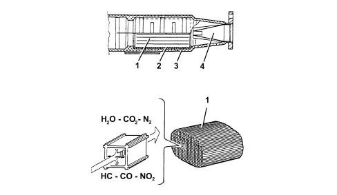
| The nobile metals in the catalytic converter suffer chemical attack if lead is present, partly due to the high temperature inside the converter. For this reason, the use of leaded fuel should be be avoided, otherwise the converter will be rapidly and irreversibly put out of service. Never use leaded fuel, even for a short time in an emergency. |