2582339 - 5505A MULTI-FUNCTION COMPONENTS
FUNCTIONS
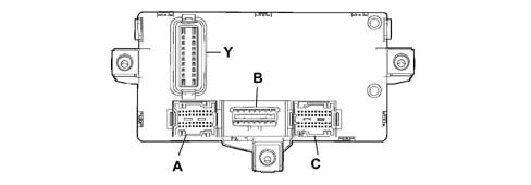
The Body Computer Noder (NBC) is mechanically fastened to the second electro-mechanical junction unit and both are located under the dashboard cover, on the driver''s side. The NBC manages a series of functions and controls relating to several devices:
- Rear side lights
- Parking lights
- Vehicle brake lights (except the third brake light)
- Rear fog lamps
- Fog lights (relay only)
- Dim dip light relay
- Heated rear windscreen timer (and fault diagnosis).
- Turn signal control and warning lights on the instrument panel
- Door lock/release control
Control unit pin out
Connector A:1 Driver''s door open signal (on door pillar)2 Left side direction indicator control3 Right rear direction indicator control4 Fuel gauge sensor signal (positive)5. Left rear side light control6. Right rear side lights control7. Anti-theft volumetric sensor serial line (function not implemented on this car)8 Driver''s door open signal9 Not connected.10 Serial line for AUTOCLOSE11. Passenger door open signal (on door pillar)12. Left rear direction indicator control13. Right side direction indicator control14. Handbrake applied signal15. Fuel gauge sensor signal (negative)16. Left rear door open signal17. Right front door release signal (NA)18. K line aggregate 319. Not connected.20. Not connected.21. Courtesy light timer control22. Right brake light control23. Courtesy light power supply24. Left front door release control signal (NA)25. Passenger side door open signal26. Right rear door open signal27. Volumetric sensor power supply (function not implemented on this car)28. Not connected.29. Not connected.30. Not connected.31. Rear fog lamp control32. Left brake light control33. Boot light power supply34. Door lock control signal - left front door (NC)35. Door lock control signal - right front door (NC)36. Boot open signal37. Not connected.38. Not connected.39. Not connected.40. Not connected.Control unit pin out
Connector B:1 K line for ABS2 Not connected.3 K line for Airbag4 Power earth5. Signal earth6. Can B7. K line for Engine Management Control Unit8 K line for immobiliser9 Predisposition for aggregates 1 (facia)10 Not connected.11. Antitheft device (function not implemented on this car)12. Predisposition for aggregates 2 (front)13. Predisposition for aggregates 3 (rear)14. Can A15. Not connected.16. Fuel systemControl unit pin out
Connector C1 Reversing signal for stalk unit2 Not connected.3 Screen fitting4 Immobilizer aerial5. Immobilizer aerial6. ABS serial line7. ABS speedometer signal8 Fog lamp relay coil control9 Main beam relay coil control10 INT power supply for speedometer generator11. Not connected.12. Not connected.13. Headlamp washer signal (Function not implemented on this car)14. Headlamp relay coil control (Function not implemented on this car)15. Earth for speedometer generator16. K line for ABS17. Speedometer signal from pulse generator18. Brake fluid level signal19. Alternator D+ signal20. Engine Control Unit diagnostics K line21. Radio frequency aerial earth22. Not connected.23. Not connected.24. Boot open signal25. Serial line for car alarm siren (Function not implemented on this car)26. Can A for electric drive node (Function not implemented on this car)27. Can B for electric drive node (Function not implemented on this car)28. Repeater for speedometer signal29. IS05 interface for dialogue between immobilizer and Engine Management Control Unit30. Right front side light control31. Radio frequency aerial32. Not connected.33. Not connected.34. Car alarm siren power supply (Function not implemented on this car)35. Predisposition for aggregates 2 (K line for diagnostics)36. CAN A from Engine Control Unit37. CAN from Engine Control Unit38. Left front turn signal control39. Right front turn signal control40. Left front side light controlControl unit pin out
Connector Y1 Door release motor control2 Light system power supply from ignition switch3 INT power supply for Instrument Panel Node4 Relay coil control5. Interior lighting and number plate light power supply6. Not connected.7. Service/SBMT service power supply8 Body Computer, immobiliser, CAN, side light, rear fog lamp power supply9 Turn signal, hazard warning light, Instrument Panel Node power supply10 Door lock earth11. Door lock motor control12. INT power suppy for Body Computer13. Main beam relay coil control14. CAN A for facia control unit15. Heated rear window relay coil control16. CAN B for Facia Control Unit17. Not connected.18. Reverse control signal19. Brake light control signal20. Door lock system power supplyControl unit pin out
Rear connector1 Not connected.2 Not connected.3 Power supply for Instrument Panel Node4 Dipped beam control signal5. CAN A for instrument panel node6. CAN B for instrument panel node7. Right turn signal control signal8 Body Computer signal earth9 Body Computer power earth10 Body Computer power earth11. Predisposition for K line aggregates 212. K line for airbag13. Rear fog lamp warning light control14. Predisposition for car alarm led power supply (Function not implemented on this car)15. Predispositio for power supplies16. Predisposition for light power supply17. Not connected.18. Not connected.19. Body Computer signal earth20. Fog light control signal21. Predisposition for heated rear window warning light control22. Predisposition for rear fog lamp warning light control23. Speedometer signal repeater24. Not connected.25. Not connected.26. Not connected.27. Not connected.28. Not connected.29. Hazard warning light warning light control30. Left turn signal control signal31. INT power supply for Instrument Panel Node32. Heated rear window control signal33. Main beam control signal34. Hazard warning light control signal35. Rear fog lamp control signal36. Instrument panel node earthSTRUCTURE
The NBC is equipped with a microprocessor and static electronic components which are responsible for:
- receiving the control signal for the switches / remote control switches (panel, steering column switch unit, etc.)
- activating the consumers (direction indicators, courtesy light, etc.)
- downloading, converting and transmitting figures to the CAN network (ABS, fuel level, etc.)
- carrying out and managing fault diagnosis (of the connectors involved) and transmitting on the CAN network.
Each input is protected by filters against electrostatic discharge or radiofrequency signals which could adversely affect the smooth operation of the device. The exterior lights are activated by semiconductor switches or relays which simultaneously check and control the function. Faults in the above mentioned bulbs or side lights are signalled to the control panel at the CAN network.The NBC comes on when the following conditions exist:
- door opening or transmitter key command received
- ignition key in ON position
The control unit remains on stand-by (in other words the energy required by the vehicle from the battery whilst the vehicle is NOT being used decreases), it ''wakes up'' when one of the above mentioned functions is activatedOPERATING PRINCIPLES
Each Body Computer is ''programmed'' by the production plant using an electronic code system. All the codes are then stored in a DATA BASE managed by the PARTS DIVISION.Therefore, when a new vehicle is handed over to a customer, the Service Network should not carry out any programming procedures. If a Body Computer is being replaced, a request should be put in to the Parts Dept. following the procedures described in the ''REPAIR PROCEDURES'' section.Downloading signal D+
The NBC control unit receives a voltage reading via a dedicated input from the alternator. The Node is thus able to manage information effectively as it changes. The body computer converts data to be sent via the CAN network for use by the relevant Nodes.1 Battery voltage value2 Ignition key state check3 Body Computer Node4 Sending recharging state at CAN line5. Instrument panel connector6. Alternator warning light signalParking lights
The parking lights are enabled if the following conditions exist: ignition key turned to PARKINGThe rear side lights, the warning light on the instrument panel and the number plate light are used as parking lights when the parking light switch (in the ignition lock barrel) is on.Vehicle brake lights
The brake lights are enabled if the following conditions exist:
- Ignition key in the ON position;
- Switch on brake pedal activated.
The car brake lights are controlled when current from the NBC is sent to the two bulbs (not the third brake light). Fault signals are sent to the instrument panel Node (NQS).Rear fog lamps
The rear fog lamps are enabled if the following conditions exist:
- Ignition key in ON position
- Rear fog lamp button activated
- Dipped beams activated or only side lights plus fog lamp (where fitted)
The control unit sends a signal to turn on the rear fog lamp warning light located in the NQS.Fog lamps
The fog lights relay feed is activated if the following conditions exist:
- Ignition key in ON position
- Side light switch activated
- Fog lamp button activated
If a fault occurs, the NBC does not send signals to the NQS but makes them available to the CAN.Main beam headlamps
The main beam headlamps relay feed is activated if the following conditions exist:
- Ignition key in ON position
- Side light switch activated
- Dipped/main beam switch activated
The main beam flasher switch may be activated for an unlimited time. The warning light on the main beam control panel is controlled via the CAN. Fault diagnosis can only be carried out on the dipped headlamps relay and made available on the CAN networkDipped headlamps ''following'' function
This function allows the dipped beams to be kept on after the key has been turned off for 30 seconds or multiiples thereof.When the main beam headlamp flasher lever is operated, the dipped headlamps can be switched on within two minutes of the ignition being switched off. Each time the lever is operated, the time the lights remain on increases by 30 seconds up to a maximum of 5 minutes. The deterrent LED also comes on to indicate the dipped headlamps follow-me-home function. If the bulbs come on, the deterrent LED comes on constantly for the duration of the function.1 Ignition key control, light control2 Body Computer Node3 Main beam / dipped headlamps status4 Instrument panel connector5. Headlamp warning light signal6. Main/dipped headlamp lightingABS EBD signal download
The NBC is equipped with an input from the ABS control unit, which allows the microprocessor to process the data, supplied via the dedicated serial line, decode it and convert it so that it can be sent to the CAN network and used by the Nodes involved.The signals are:
- ABS EBD system anomaly
- Car speed
1 ABS EBD control unit2 ABS EBD TC control unit connection via dedicated serial line3 Body Computer Node4 Transmission to CAN network of ABS EBD control unit fault status5. ABS EBD TC failure warning light status, warning light failure6. Instrument panel connector7. ABS EBD TC failure warning light onHeated rear windscreen timer
The heated rear windscreen timer relay is activated when the following conditions exist:
- Ignition key in the ON position;
- Heated rear windscreen button (active type return) with timer activated.
Activation only occurs when the switch is released to prevent the heated rear windscreen being on constantly if there is a short circuit in the NBC intake circuit.The NBC output which operates the heated rear windscreen can be deactivated:
- Manually, by pressing the control switch or if there is no ignition ON signal
- Automatically, after 30 minutes of actual heated rear windscreen operation.
The automatic operation of the heated rear windscreen is basically connected to the:
| ... DATA ERROR - CROPPED TEXT | Ошибка данных - Текст обрезан ... |
|---|