2585407 - INTRODUCTION - A(B.S. ANTI-LOCK BRAKING SYSTEM .)
INTRODUCTION
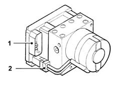
The brake system must be big enough to deal with the weight of the car when fully laden and the maximum possible ground/tyre grip coefficient. The aim is to ensure effective slowing or halting in the shortest possible time under all driving conditions.Brake system size may be increased to deal with the most common conditions of partial load and reduced grip.Under these circumstances, application of maximum braking force leads to the brakes locking immediately. The grip-friction coefficent is therefore reduced and braking efficiency decreases.If car motion is to be halted quickly and effectively in all situations, the wheels must be kept rolling. Depite this, for design reasons, the braking force applied to the linings is often too much for the car''s normal kerb weight and normal grip coefficients.The wheels must therefore be prevented from locking by means of an electronic anti-lock braking device that is built into the car''s braking system.Becuase it is not possible to assess grip conditions beforehand, braking efficiency can be checked only after recording the effects of intial tyre slip brought about by a braking force that is excessive for the existing grip coefficient.Once this effect has been recorded by special sensors, braking force can be modulated by the action of a series of solenoids and scavenging pumps that act on the braking circuit and are governed by an electronic control unit.The TEVES MK20 ABS with EBD is integral with: the brake cylinder (2), brake servo (3), front brake calipers (6), rear drums (12) of the conventional braking system and consists of:
- a control unit (1) that contains an electronic control unit (A), a hydraulic section (B) that modulates braking pressure via eight solenoids, two per wheel, and a scavenging pump (C);
- a warning light (7) on the control panel that indicates whether the system is working efficiently;
- four ''active'' type sensors, two at the front (5) and two at the rear (11) which detect the angular rotation speed of the wheels.
- a switch on brake pedal (8) that records braking condition.
The system is completed by hydraulic system lines, special wiring and a tester connection point.If a fault is present, the ABS is immediately deactivatedInformation on faults present may be read by connecting a computerised tester station to the tester connection point.1 Hydraulic control unit2 Brake pump3 Brake servo4 Brake fluid reservoir5. Front active sensors6. Front disc brakes7. Fault warning light8 Brake light switch9 Parking brake control lever10 Rear active sensors11. Rear drum brakesControl unit
The electronic control unit (ECU) consists of:
- an input circuit with a 25-pin connector for downloading of digital signals from the active sensors.
- integrated circuits for processing of input signals and memory management
- a data memory
- a power stage designed to control modulation solenoids and scavenging pump motor via connector (2) and the fault warning light.
Teves MK20 control unit pin-out
Control unit side connector1 Left front sensor signal2 Left front sensor power supply3 N.C.4 N.C.5. Left rear sensor signal6. Left rear sensor power supply7. Tester connection8 Signal earth9 Power supply from battery10 N.C.11. N.C.12. N.C.13. Ignition-operated power supply (+15)14. N.C.15. System failure warning lights (ABS - EBD)16. N.C.17. N.C.18. Brake pedal switch19. Right front sensor signal20. Right front sensor power supply21. N.C.22. Right rear sensor power supply23. Left rear sensor signal24. Power earth25. Power supply from battery (+30)BRAKE light switch
The brake pedal operating signal reaches the control unit via the connection of switch/selector (1), wihch controls the car brake lights.This information is useful for controlling braking under certain conditions, e.g. when the car is strongly braked after an abrupt acceleration that makes the wheels skid - or in the case of irregular road surfaces (corrugations, steps) that can cause wheel speed to change for reasons unconnected to the braking manoevre.Under these conditions, the microprocessors implement a strategy dependent upon changes in wheel speeds at these given moments in order to restore the braking manoeuvre to within correct parameters.System efficiency is not affected if the brake pedal switch is not connected to the control unit under these specific brake control conditions.For this reason, the warning light does not come on and the ABS is disabled.ABS failure warning light
Under conditions of inefficient operation, the red warning light (shown in the figure) goes offWhen the ignition key is turned to MAR to start the car, the control unit runs a static self-check for about 4 seconds during which the warning light remains on.The indicator goes off if no anomalies are detected after this time.The control unit runs continuous self-checking cycles while the car is in motion. If an error is detected, the warning light comes on and the ABS is disabled. The conventional braking system works as normal.ABS failure warning light
The fault indication warning light is a SMART type.The warning light takes the form of a led (D2) controlled by an electronic circuit, which consists of two resistances R1 and R2 protected by a diode (D1). The diode is made as shown in the diagram alongside and allows the warning light to come on if the ABS is faulty or if the connection between pin 15 of control unit (1) and instrument panel (2) is broken or short-circuited to earth.EBD function
The Teves MK20 ABS used on this car incorporates an EBD function (Electronic Brakeforce Distribution) that distributes pressure acting on the brakes over the front and rear axes hydraulically.This function is controlled by the ABS electronic control unit, which uses the ABS sensors and actuators to calculate and implement brake pressure distribution.The introduction of this function makes the conventional mechanical load proportiioning valve superfluous and this has been removed from the rear brake hydraulic circuit.The EBD function also allows optimal use of the rear brakes because the device is able to send the ideal brake pressure at all times to prevent the rear wheels locking if grip is insufficient.The electronic control unit continually compares front and rear wheel speed by means of the speed sensors and controls the hydraulic unit to prevent the rear wheels locking.The graph below shows how the EBD function (curve D) works in relation to pressure in the braking system (curve D), ideal pressure to the rear axle brakes (curve B) and pressure reduction to the rear axle brakes normally implemented by the conventional load proportioning valve (curve C).1 Rear axle brake force2 Front axle brake forceA. Distribution implemented by the braking systemB. Ideal distributionC. Distribution implemented by the mechanical load proportioning valveD. EBD controlEBD function
As you can see, the EBD function of the ABS is able to adjust to an ideal pressure cuve and make the most of available grip under all braking conditions.By making the EBD function part of the normal ABS operating system, both strategies are able to work in tandem; the system therefore works normally to keep the rear wheels rolling within limits very close to ideal values. The ABS strategy can cut in when a rear wheel tends to lock (e.g. changeover to a surface with lower grip).The following graph shows the brake pressure implementation strategy controlled by the electronic control unit on the basis of input data. This is represented by a signal indicating wheel rotation speed on both axes.1 EBD control2 ABS controlE. Rear wheel speedF. Front wheel speedG. Front wheel pressureH. Rear wheel pressureEBD system failure warning light
A fault in the EBD system is indicated by the brake system warning light (1) and ABS fault indiator (2) lighting up on the instrument panel.If warning light (1) lights up on the instrument panel but ABS warning light (2) does not come on too, this does not indicate a fault in the EBD fuction but one of the other faults the warning light is designed to indicate (low brake fluid level, handbrake on).If ABS warning light (2) comes on alone without warning light (1) coming on, this indicates a fault in the ABS as described i the specific chapter, but the EBD function is not affected.If the EBD function is faulty, brakeforce is no longer distributed over the front and rear axles. This means that the rear wheels are at risk of locking under certain braking conditions.Active sensors
The Teves MK20 ABS uses active sensors (1) to detect wheel speed.These sensors are fitted in front of the wheel hub and to the rear of the drum casing. They are supplied electrically by the ABS.Active sensors
The sensors face a multipolar ring (2), which is fitted to the wheel bearing seal at the front and press-fitted to the hub at the rear.Active sensors
The use of active sensors offers the following advantages compared with conventional magnetic induction sensors:
- improves the negative effects of the gap between the sensor and the magnetic ring
- improves immunity to electromagnetic fields
- improves sensor detection ability at low speeds (down to zero km/h)
- reduces car weight and bulk
In order to ensure correct signals, the specified gap between the end of the sensor and the multipolar ring must be between:0.4 and 1.5 mm for the front wheels0.4 and 1.2 mm for the rear wheels | Because this gap cannot be adjusted or measured if malfunction is suspected, check sensor condition visually to ensure they do not show signs of wear or damage. In this case, they must be replaced. |
| Whenever an rpm sensor is fitted, spread with water-repellent grease so that it is not destroyed by removal due to the effect of thermal changes. |
Introduction to the system
The signals sent by the rpm sensors on the wheels are square wave signals1 Effective car speed2 Reference car speed3 Peripheral wheel speed4 Wheel acceleration/deceleration5. Brake circuit pressure6. Permissible acceleration band7. Permissible deceleration bandIntroduction to the system
Frequency is directly proportional to wheel rotation speed and interpreted by the control unit to determine individual wheel speed values (3) and acceleration and deceleration values (4).Reference speed (2) is processed from a combination of individual peripheral wheel speeds. This is continuously updated to provide an indication of effective vehicle speed (1).The control unit memory contains two threshold acceleration/deceleration values (6) and (7) that should never be exceeded by each individual wheel. Effective wheel roll during braking is kept under control by continual monitoring of wheel deceleration/acceleration values.The wheels can decelerate to different extents when the driver presses the brake pedal.The system does not cut in to control the system if the car slows down or halts with deceleration within the permissible stored band.If excessive braking force makes the wheel speed drop faster than the car reference speed, the system begins to compute rate of deceleration (point A).When the programmed deceleration threshold (7) is exceeded, the system cuts in to control the solenoids and reduce pressure (point B).Once pressure has been reduced, the now-unbraked wheel reverses its tendency to lock and picks up speed again after an initial few moments when deceleration continues to increase due to system inertia.When deceleration is restored to a level within the permissible range (7), the control system adopts a different strategy and instigates the pressure maintenance stage (point C).If wheel has not been restored within a preset time (t), a new pressure preduce stage is instigated.The wheel normally picks up speed until it exceeds the reference speed. A new braking cycle now begins (point D). This features three modulation stages to reduce, maintain or restore the pressure exerted by the driver on the brake pedal to the brake calipers.The strategy described is naturally linked to tyre dynamic behaviour on the basis of different grip coefficients and the respective deceleration/acceleration thresholds at different speeds.The number and frequency of corrective interventions is determined by the dynamic behaviour of a chain made up of the braking circuit and ABS, and to an even greater extent by the tyre/road surface grip coefficient.The system may cut in as many as six-eight times per second when braking on dry asphalt. This frequency drops considerably when the car is driven on ice or a wet surface.The electronic control unit controls the various stages to supply the solenoids with pulses of different current intensities. | During the intervention cycle, the brake pedal moves slightly according to the increase or decrease in controlled pressure. |
If one of the tyres is deflated, the ABS cuts in to control braking conditions if necessary.The ABS is also active when the car brakes while reversing.The device normally ceases to intervene at speeds below 0.6 km/h to allow the wheels to lock completely when the car is at a standstill. | Because the parameters controlled by the control unit (wheel speed and acceleration) are influenced by wheel/tyre inertia, cars with an ABS should be fitted only with rims, tyres and brake linings recommended and approved by the Manufacturer. |
| ... DATA ERROR - CROPPED TEXT | Ошибка данных - Текст обрезан ... |
|---|