2585417 - Introduction - ELECTRICAL CIRCUIT FOR INSTRUMENTS/INDICATORS
FUNCTIONS
'VeNICE' stands for Vehicle Network Integration Component Electronics.For this reason, 'VeNICE' is a powerful software and hardware solution which efficiently manages the resources in the vehicle allowing:
- data to be shared between the various ECUs;
- several ECUs to be integrated in a network;
- high data exchange speed in the network;
- cost-effective solutions, since the number of wiring harnesses and connectors are considerably reduced in the vehicle;
- a higher standard in terms of quality and reliability.
FUNCTIONS
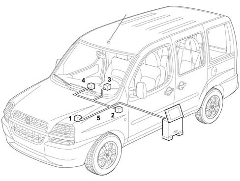
In its most comprehensive configuration, the VeNICE system consists of the following parts:
- engine bay control unit (1) (electromechanical)
- facia node (2) (electromechanical/electronic)
- instrument panel node (3) (electronic)
- control panel node (4) (electromechanical and electronic)
- wiring (5)
SYSTEM ARCHITECTURE IN GENERAL
The various 'Node' ECUs in the system are connected to the CAN (17) via communication interfaces called 'Transceivers'.The interfaces are built into the ECUs and form gates for sending/reading data on the CAN (12) or on the serial lines.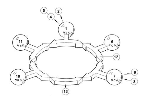
SYSTEM ARCHITECTURE IN GENERAL
The following figure illustrates the communication interface: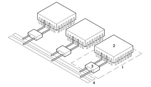
SYSTEM ARCHITECTURE IN GENERAL
System designers assign control functions to the Body Computer in the VeNICE architecture (see relevant assembly for details on the NBC functions).The additional Body Computer functions provide information on:
- network activity status;
- the functional failure status of individual node ECUs;
- CAN failure.
OPERATING PRINCIPLES
Each 'Node' ECU processes the various signals from the respective sensors in order to manage themselves and the other ECUs.For greater clarity, the following drawings illustrates a possible data sharing procedure between units connected in a network.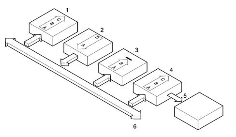
OPERATING PRINCIPLES
Example:
- The Engine control node (2) sends an rpm signal to the network (6).
- The Instrument panel node (4) reads the data and uses it to control the rev gauge to inform the driver of the engine rpm.
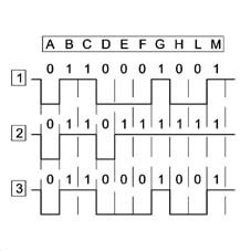
DATA TRANSMISSION PRIORITY
The VeNICE system employs a 'CSMA/CD' - Carrier Sense Multiple Access / Collision Avoiding - mechanism to allow several 'Node' ECUs simultaneous access to the network (double wire).The CAN system is used because various ECUs interface and consequently a high number of signals is managed. A double copper wire CAN is therefore used. One wire is associated to the high level (H) and the other to the low level (L). The combined use of two wires and differential signals offers very strong signal communication even in environments with high electromagnetic interference.The maximum number of distinct IDs for the CAN standard is 2032.The following diagram shows simultaneous data transmission in the network to illustrate the transmission priority mechanism between nodes.