2585419 - Introduction - EXTERIOR LIGHTING
LOCATION OF COMPONENTS ON VEHICLE
FUNCTIONS
The vehicle''s exterior lighting system has been designed with two aims in mind:
- ensuring maximum efficiency in terms of complying with international regulations which define the illumination specifications of the various components
- to blend with the design of the vehicle so that the various components enhance the overall image.
PERFORMANCE
The nominal operating voltage for the system can vary from 9 to 16 volts.STRUCTURE
The front light cluster consists of the following components:A light unit which includes:
- A housing for the fog light and the lens cover which focuses the light beam.
- A housing for the dipped headlamp and the lens cover which focuses the light beam and an internal element for adjusting the light beam geometry to meet standards.
- A housing for the direction indicator with an orange reflector lens cover.
- A housing for the main beam headlamp and parabola with mirrored surface.
- A housing for the side light and the reflector lens cover.
The following are also present:
- A fog light bulb 12 Volt - 55 Watt (1)
- A dipped headlamp bulb 12 Volt - 55 Watt (2)
- A direction indicator bulb 12 Volt - 5 Watt (3)
- A main beam headlamp bulb 12 Volt - 55 Watt (4)
- A side light bulb 12 Volt - 5 Watt

OPERATING PRINCIPLES
The user can operate a ring at the end of the left steering wheel stalk to turn on the side lights, dipped beams and main beams (fixed or flashing position).The same stalk also controls turns signals for lane changes and foglamp/rear foglamp enablement (for further details, see stalk unit 5550A and Body Computer description)FOLLOW ME HOME FUNCTION
This is a strategy available on the SX trim level which allows the dipped headlamps to remain on, even with the ignition switched off, for a pre-set time.This function is particularly useful, for example, after parking the car in a garage or in poorly lit areas.The function is activated, after the key off, for a maximum of 2 minutes; within this period, pulling the left steering column switch unit lever in the direction of the steering wheel activates the dipped headlamps for 30 seconds; each time the lever is operated, the time increases by a further 30 seconds, up to a maximum of 5 minutes.Pins
A connection on the light cluster casing controls the side lights, dipped headlamps, main beam headlamps, direction indicators and light beam vertical adjustment
HEADLAMP ALIGNMENT ADJUSTMENT
LOCATION OF HEADLAMP ALIGNMENT ADJUSTMENT COMPONENTS ON VEHICLE
Operation
The headlamp alignment adjustment device is designed to correctly position the dipped headlamp light beam, in a vertical direction, irrespective of the load on the axles.Operating methods
It is possible to vary the angle of the light clusters with 4 standard positions by acting on the two switches on the left hand side of the instrument panel.The positions are shown in a special display in the instrument panel.The table below illustrates the three positions which can be selected according to the vehicle load conditions:| Headlamp alignment position | Panorama version | Cargo version |
|---|---|---|
| - | Load status | Load status |
| 0 | empty, driver, driver + front passenger | empty, driver |
| relay | all seats occupied | - |
| relay | all seats occupied + luggage compartment loaded to the maximum technically permissible limit (180 kg) | - |
| 3 | driver + luggage compartment loaded to maximum limit on the rear axle (430 kg) | driver + luggage compartment loaded to maximum technically permissible limit and max on the rear axle (550 kg) |
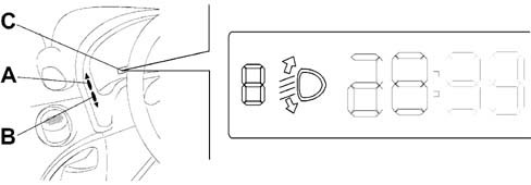
Operating methods
To carry out the headlamp alignment adjustment, proceed as described below:
- Press button A and keep it pressed until there is an increase by one position (e.g. 0>1, 1>2)
- Press button B and keep it pressed until there is an increase by one position (e.g. 2>1, 1>0)
TAIL-LIGHT CLUSTER
View of tail-light cluster
TAIL-LIGHT CLUSTER
View of connectors and internal diagram
TAIL-LIGHT CLUSTER
Vehicle side view
TAIL-LIGHT CLUSTER
The vehicle''s exterior lighting system has been designed with two aims in mind:
- Ensuring maximum efficiency in terms of complying with international regulations which define the illumination specifications of the various components
- To blend in with vehicle design so that the various components enhance the image.
PERFORMANCE
The nominal operating voltage for the system can vary from 9 to 16 volts.Power of bulbs for brake light, direction indicator, reversing light, rear fog lamp 21 Watt - 12 Volt.Power of bulb for side light 10 Watt - 12 VoltSTRUCTURE
The right rear light cluster consists of the following components:
- A light unit which includes:
- A housing for the side light (1) with a reflector lens cover and brake light.
- A housing for the direction indicator (3) with a reflector lens cover.
- A housing for the reversing light (4) with a reflector lens cover.
The left rear light cluster consists of the following components:
- A light unit which includes:
- A housing for the side light (1) with a reflector lens cover.
- A housing for the direction indicator (3) with a reflector lens cover.
- A housing for the rear fog lamp (4) with a reflector lens cover.
- A housing for the reversing light
PINS
There is a connection on the rear light cluster casing:Connection| PIN | Operation |
|---|---|
| relay | Side light control |
| relay | Brake light control |
| 3 | Turn signal control |
| 4 | Reversing light control |
| 5 | Rear fog lamp earth (left) |
| 6 | Earth |