2585420 - Introduction - MANOEUVRING AND WARNING SIGNALS
STALK UNIT
LOCATION OF COMPONENTS ON VEHICLE
FUNCTIONS
The steering column switch unit is designed to produce the following commands:
- Side lights, dipped headlamps, main beam headlamps;
- Headlamp flasher;
- Direction indicators;
- Windscreen wash/wipe;
- Rearscreen wash/wipe
STRUCTURE
The steering column switch unit, as represented diagrammatically below, consists of the following components:Front view
FUNCTIONS
It is a part of the steering column switch unit containing the electrical circuits and the switching and automatic release mechanisms which return the left lever to the rest position once the steering wheel has been realigned.The typical angles are listed below:
- Engagment angle 80° ± 5°;
- Release angle 60° ± 5°.
COMPOSITION
The front part of the casing houses the release wheel or the air bag clock spring which provides the interface with the steering wheel.At the rear is the manifold with a retaining band for fastening it to the steering column and additional attachments which guarantee the axial and angular position of the steering column switch unit on the steering column.The steering column switch unit casing contains the fastenings for the upper/lower half casing trims.The rear of the casing contains the housigns for the electrical connectors.FUNCTIONS
The electronic module inside the steering column switch unit casing has the task of controlling the following functions:
- Windscreen wiper (frequency for de-luxe version only);
- Rearscreen wiper (frequency for de-luxe version only);
- Windscreen washer function ('smart' washing for all versions);
- Rearscreen washer function ('smart' washing for de-luxe version only)
Smart washing
Smart washing makes it possible to operate the water jet and the wipers in one single movement; the wipers start working 1 second after the lever which controls the jet of water is operated and they stop working 4 strokes after the control has been released.The smart washing function is valid for both the windscreen washer and the rearscreen washer.There are two smart washing logics according to the trim level (standard or de-luxe) with the operating modes described in the diagrams:Basic trim level
Smart washing
De-Luxe trim level
STRUCTURE
The electronic module consists of an electronic control unit electrically connected to the steering column switch unit casing by means of special terminals and mechanically fastened to it so that it can be replaced if faulty.WIRING CIRCUIT DIAGRAM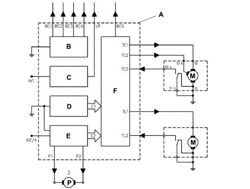
STRUCTURE
The following interfaces are defined with reference to the wiring diagram illustrated:| Interface | Signal | Description |
|---|---|---|
| BC1 | OUT | Left direction indicator operation request to body computer |
| BC2 | OUT | Right direction indicator operation request to body computer |
| BC3 | OUT | Dipped headlamps operation request to body computer |
| BC4 | OUT | Main beam headlamps operation request to body computer |
| LP | OUT | Direct operation of no. plate light and passenger compartment controls lights, also acquired from body computer for operating the side lights. |
| TC2 | OUT | Windscreen wiper 2nd speed command Nominal absorption from 1.7 to 4 Ampere, with the windscreen wiper motor stopped the absorption increases to 32.4 Ampere with a voltage value of 13.5 Volt. |
| TC3 | IN | Windscreen wiper zeroing cam, this consists of a switch fitted on the motor which is normally open when the windscreen wiper is in the rest position (wiper blades parked at bottom) and is active when earthed. |
| TL1 | OUT | Rearscreen wiper operation. Absorption from 1 to 2.5 Ampere, with the windscreen wiper motor stopped the absorption increases to 14 Ampere, with a voltage value of 13.5 Volt. |
| TL2 | IN | Rearscreen wiper zeroing cam, this consists of a switch fitted to the motor which is normally open when the rearscreen wiper is in the rest position (wiper blades parked at bottom) and is active when earthed. |
| P1 | OUT | Windscreen/rearscreen washer pump operation Absorption from 2.5 to 3.5 Ampere, with the windscreen wiper motor stopped the absorption increases to 11.8 Ampere, with a voltage value of 13.5 Volt. |
| P2 | OUT | Windscreen/rearscreen washer pump operation Absorption from 2.5 to 3.5 Ampere, with the windscreen wiper motor stopped the absorption increases to 11.8 Ampere, with a voltage value of 13.5 Volt. |
| C1 | IN | This represents the set of wiping and washing function commands to the electric module. |
| C2 | IN | This represents the set of wiping and washing function commands to the electric module. |
SPECIFICATIONS:
FUNCTIONS
SPECIFICATIONS:
The left lever has the task of controlling:
- The main lights switch (side lights);
- Dipped/main beam headlamps switch;
- The headlamp flasher on main beam;
- Direction indicators and lane chage.
STRUCTURE
The left lever consists of two parts:
- A lever for controlling the main beam headlamps and the direction indicator;
- A ring nut at the end of the actual lever for controlling the side lights and the dipped headlamps.
OPERATING METHODS
The operation of the exterior lights is controlled by the right lever as described below.Main lights switch
The lights control is at the end of the lever and is activated by rotating a ring nut.There are 3 stable positions for the ring nut when it is rotated in an anti-clockwise direction:
- Zero position (0), in this rest position, the lights are off;
- Position one (1), side lights on;
- Position two (2), side lights and dipped headlamps on, plus the go ahead to switch on or flash the main beam headlamps and the rear fog lamp/fog light.
Dipped/main beam headlamps switch
By moving the lever starting from position (3) in the opposite direction to the steering wheel rim (movement perpendicular to the steering wheel plane) position (4) is created, i.e. the main beam headlamps stable position. During this switching stage from dipped to main beam headlamps and viceversa there is no break in the electrical contact causing the lights to go out (preventative safety).Control for headlamp flasher
By moving the lever starting from position (2) towards the steering wheel rim (movement perpendicular to the steering wheel plane) position (4) is produced, i.e. the main beam headlamps unstable (flashing) position, when the lever is released, it returns to the rest position.Control for direction indicators and lane change
The direction indicators are operated by moving the lever on the steering wheel plane in two directions - clockwise and anti-clockwise (5) and (6).The movement of the control, in each direction, involves two distinct activating modes for the same electrical contact, one defined as UNSTABLE (lane change) and one defined as STABLE (change of direction).The lane change function is activated through a lesser angular movement than that required for activating the change in direction.The automatic release device intervenes for each stable position of the direction indicators and has the function of returning the lever to the rest position (position 2) after the steering wheel has been realigned.FUNCTIONS
The diagram below illustrates the functions performed by the right lever.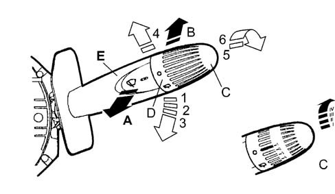
FUNCTIONS
The right lever has the task of controlling:
- The winscreen wiper;
- The windscreen washer;
- The rearscreen wiper;
- The rearscreen washer.
- The adjustment of the frequency of the windscreen/rearscreen stroke (de-luxe version only)
STRUCTURE
The left lever consists of two parts:
- A lever for controlling the front and rear wipers;
- A ring nut at the end of the lever for adjusting the frequency of the strokes (de-luxe version only).
WINDSCREEN AND REARSCREEN WIPER OPERATING METHODS
The operation of the windscreen wiper and the rearscreen wiper is controlled by the right lever as described below.Windscreen wiper operation
The operation is achieved by moving the lever on the steering wheel, there are 5 different positions:| POS 0 | No circuit switched on | (stable) | [Rest position] |
| POS 1 | Intermittent | (stable) | [clockwise direction] |
| POS 2 | Continuous 1st speed | (stable) | [clockwise direction] |
| POS 3 | Continuous 2nd speed | (stable) | [clockwise direction] |
| POS 4 | Anti-panic position | (unstable) | [anti-clockwise direction] |

Windscreen washer control
The windscreen washer is operated by pulling the lever towards the steering wheel, the control is UNSTABLE as a result of which when the lever is released it returns to the rest position.The operation of the control involves activating the windscreen wiper in accordance with the 'smart washing' function described under the ELECTRONIC MODULE.Rearscreen wiper control
The control for the rearscreen wiper is at the end of the right lever and is operated by turning a special ring nut. The control has two STABLE positions and is turned in a clockwise direction:Basic trim level:
- Pos. 0 = No circuit switched on;
- Pos. 1 = Rearscreen wiper operating continuously
De-Luxe trim level:
- Pos. 0 = No circuit switched on;
- Pos. 1 = Rearscreen wiper operating intermittently
Rearscreen washer control
It is operated by pushing the right lever towards the dashboard, the position is UNSTABLE as a result of which when the lever is released it returns to the rest position.The operation of the control involves the activation of the rearscreen wiper in continuous mode on the basic trim level and with the 'smart washing' function described under the ELECTRONIC MODULE.PINS
The pin-outs for the connectors on the steering column switch unit are illustrated below.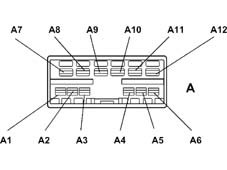
PINS
Connector A| Pin | Operation | Rated current (A) |
|---|---|---|
| A1 | Horn output | 0.2 |
| A2 | Standard anti-theft device preparation output | 0.2 |
| A3 | Spare N.C | --- |
| A4 | Spare N.C | --- |
| A6 | Windscreen wiper zeroing input | 0.07 |
| A7 | Power earth input | 2.5 - 3.5 |
| A8 | 2nd windscreen wiper speed output | 1.7 - 4.0 |
| A9 | 1st windscreen wiper speed output | 1.1 - 2.9 |
| A10 | Rearscreen washer two-way pump control output (positive) | 2.5 - 3.5 |
| A11 | Windscreen wiper/pump INT/A input | 6.5 |
| A12 | Rearscreen washer two-way pump control output (positive) | 2.5 - 3.5 |

PINS
Connector B| Pin | Operation | Rated current (A) |
|---|---|---|
| B1 | Right turn signal control | 0.05 |
| B2 | Main beam headlamp/flasher control | 0.05 |
| B3 | Dipped headlamps control | 0.05 |
| B4 | Rear fog lamp go ahead | 0.2 |
| B5 | INT for side lights operation | 2.0 |
| B6 | Side lights control to Body C. | 0.05 |

PINS
Connector C| Pin | Operation | Rated current (A) |
|---|---|---|
| C1 | Available | --- |
| C2 | Rearscreen wiper supply | 3.5 |
| C3 | Rearscreen wiper motor supply | 3.5 |
| C4 | Rearscreen zeroing input | 3.5 |
| C5 | Signal earth | 0.5 |
| C6 | Left hand turn signal control | 0.05 |