2585430 - INTRODUCTION - PANELS AND FRAME
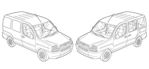
The design of the vehicle gives it a unique personality with all the bodywork variants that respond to the multitude of different usages.At the front the grille and the headlamps are surrounded by plastic that protects against impacts at low speed.The side panel features the rounded shape of the windows in the front doors and the extensive rear glass which produce a sensation of light and brightness that contributes to driving comfort.The sliding side doors, the two rear asymmetrical doors or the tailgate do not alter the sense of harmony of the model but fit in naturally with the exterior design of the vehicle.Drag coefficienct (cx) 0.32PASSIVE SAFETY
The main objective of the features adopted in terms of passive safety is to create a survival chamber which, in the case of an accident, offers the passengers effective protection.The bodyshell of the veihcle has been designed for controlled deformation in the case of front, side and rear impact and to absorb the energy developed by the impact without adversely affecting the vital spaces in the passenger compartment.BENDING AND TORSIONAL STRENGTH
The high torsional and bending strength of the bodyshell guarantees the vehicle excellent passive resistance qualities producing a sensation of solidness and comfort when driving.These excellent values also guarantee that the original specifications of the bodyshell are maintained over a period of time and there are no structural weaknesses that could adversely affect safety.Torsional rigidity.
| VEHICLE TRIM LEVEL | daNm/rad |
|---|
| 1. Stripped bodyshell + windscreen | 88700 |
| 2. Like 1 + swing rear doors | 98400 |
| 3. Like 2 + front doors | 101900 |
| 4. Like 3 + sliding side doors | 107300 |
Bending rigidity
| VEHICLE TRIM LEVEL | daN/mm |
|---|
| 1. Stripped bodyshell + windscreen | 1500 |
| 2. Like 1 + swing rear doors | m |
| 3. Like 2 + front doors | 1620 |
| 4. Like 3 + sliding side doors | 1890 |
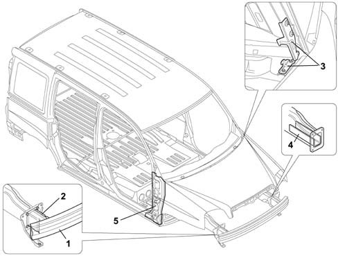
RESISTANCE TO FRONT IMPACTS
The main operations to the bodyshell for resistance to front impacts involve:
- front crossmember
- crash-box
- bonnet retaining hooks
- reinforcements on struts
- reinforcements on front pillars
RESISTANCE TO FRONT IMPACTS
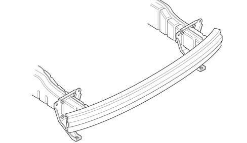
The vehicle comforms with front impact standard ECE R94 with the barrier offset in relation to the axis of the vehicle (cover of front section equal to 40%) at 56 Km/hIn this test checks are carried out on both structural measurements (made on the vehicle) and biomechanical ones (made on the occupant); the effects on the occupant are measured using special dummies.Front crossmember
View of front crossmember with crash-boxFront crossmember
The front crossmember and the crash-box are a new feature in the range of group vehicles because the structural elements are integrated and fitted on the bodyshell using bolts.They have been designed to reduce repair costs following impacts at low speed.In the case of a front impact at 16 km/h with an offset barrier (front covering of the vehicle equal to 40%) only these two components are deformed.The particular shape of the crossmember and the material from which it is made (highly resistant steel) guarantee that with this type of impact there is the minimum intrusion protecting the mechanical components. | If the body is repaired, the structural reinforcements should always be replaced if deformed. |
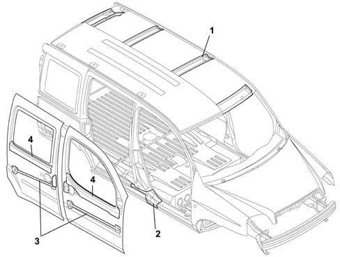
RESISTANCE TO SIDE IMPACTS
In the case of side impacts the bodyshell is capable of offering a high level of safety, providing programmed deformation which does not adversely affect the survival chamber.The above has been achieved by:
- reinforcing the centre pillar
- adopting connecting ribs between the side pillars
- with the anti-intrusion bars and waist reinforcements on the doors
RESISTANCE TO SIDE IMPACTS
The vehicle conforms to side impact regulation ECE R 95 against a deformable barrier (centred in relation to the front seat positioned midway and adjusted to the lowest position) at 50 Km/h. | If the body is repaired, the structural reinforcements should always be replaced if deformed. |
RESISTANCE TO REAR IMPACTS
The main operations to the bodyshell for resistance to rear impacts involve:
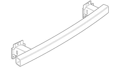
- rear crossmember
- crash-box
- reinforcements on floor panel
RESISTANCE TO REAR IMPACTS
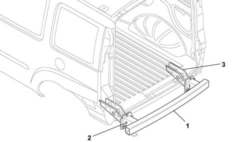
The vehicle conforms to the "Japanese" rear impact standards against a rigid barrier at 50 Km/h (covering of the rear of the vehicle equal to 100%).RESISTANCE TO REAR IMPACTS
The rear crossmember and the crash-box are a new feature in the range of group vehicles because the structural elements are integrated and fitted on the bodyshell using bolts.They have been designed to reduce repair costs following impacts at low speed.In the case of a rear impact at 16 km/h against an offset barrier (rear covering of the vehicle equal to 40%) the floor panel is not deformed. | If the body is repaired, the structural reinforcements should always be replaced if deformed. |
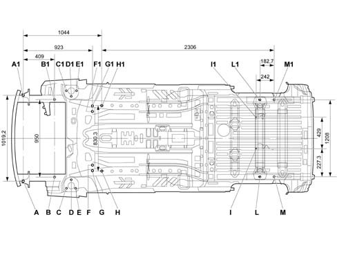
DIAGRAM FOR CHECKING UNDERBODY
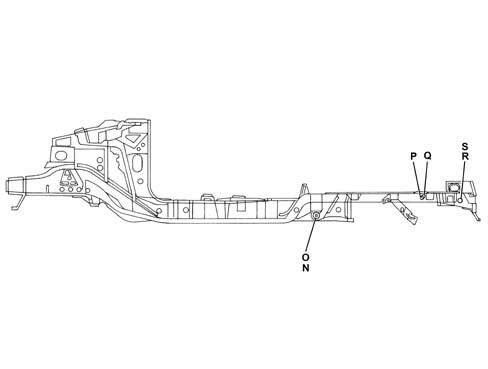
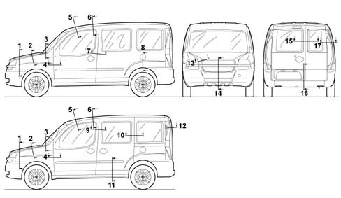
This chapter shows the specified bodyshell dimensions to ensure the best results are achieved when carrying out repair operations.Perspective viewDIAGRAM FOR CHECKING UNDERBODY
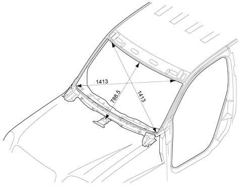
Side viewWINDSCREEN COMPARTMENT DIMENSIONS MEASUREMENT
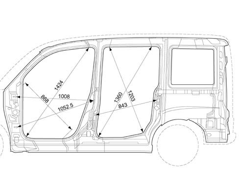
The distances are expressed in millimetres with a tolerance of about 2 mmDOOR HOUSING DIMENSIONS MEASUREMENT
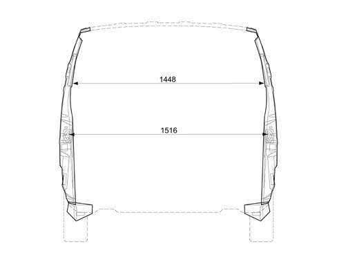
The distances are expressed in millimetres with a tolerance of about 2 mmMEASUREMENT OF DIMENSIONS OF COMPARTMENT BETWEEN CENTRE PILLARS
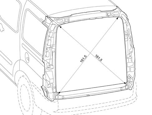
The distances are expressed in millimetres with a tolerance of about 2 mmREAR COMPARTMENT DIMENSIONS MEASUREMENT
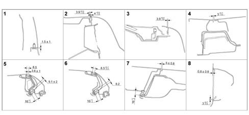
The distances are expressed in millimetres with a tolerance of about 2 mmDIMENSIONS FOR THE ADJUSTMENT OF MOBILE PARTS
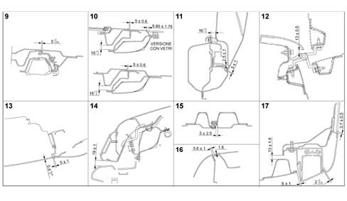
To facilitate the operations of refitting the moving parts, the existing gaps are shown (in millimetres) to allow appropriate adjustment.The adjustment procedures are described in the sections describing the removing and refitting of the moving parts.DIMENSIONS FOR THE ADJUSTMENT OF MOVING PARTS
Sections from 1 to 8DIMENSIONS FOR THE ADJUSTMENT OF MOVING PARTS
Sections from 9 to 17SOUND INSULATION
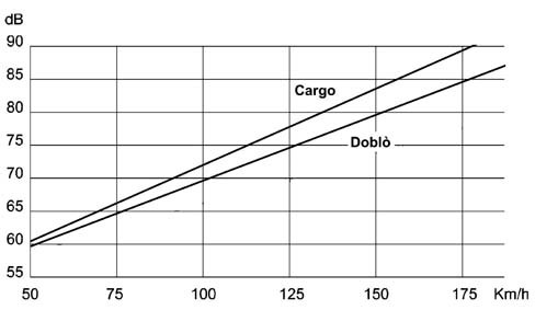
The CEE standards set an exterior noise level for the vehicle of 74 decibels, whilst for the interior of the passenger compartment, at a speed of 120 Km/h in fifth gear it is 73 decibels (76 decibels for the CARGO).The improvement in driving comfort, in terms of quietness and quality inside the passenger compartment, has been mainly achieved through working on the following areas where noise is produced:
All the engine types used on the vehicle belong to a new generation with technological features designed to improve acoustics and vibrations.This same concept it also valid for the drive transmission components, the suspension and the bodyshell mountings.Diagram showing internal noise figures for slow acceleration in 5th speed:SOUND INSULATION
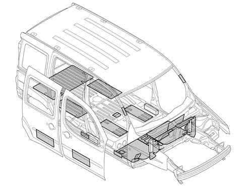
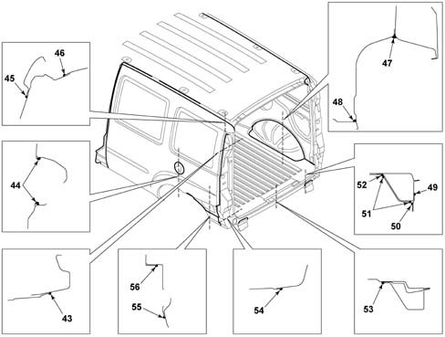
Diagram showing application of sound insulation and thermo-expandable productsSOUND INSULATION
The sound insulation material mainly comprises bitumen.Their task is to dampen the noise coming from mechanical vibrations in areas such as, for example, the underbody and the interior of the doors.The thermo-expandable materials are made up of rubbers or synthetic resins and have the task of damping the box sections to eliminate acoustic propagation (noise, whilstling).When the bodyshell goes in the ovens during the painting cycle these materials expand and vulcanize adhering to the inner surfaces of the panels with which they come into contact, completely filling the box section cavities. | taking into consideration the high level of acoustic comfort achieved, the specifications adopted during manufacture must be restored exactly in the event of repair. |
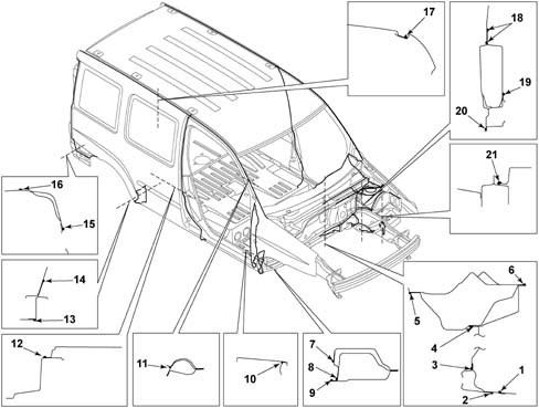
Diagram 1 - application of sealantsSOUND INSULATION
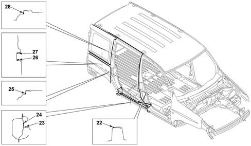
Diagram 2 - application of sealantsSOUND INSULATION
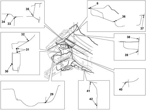
Diagram 3 - application of sealantsSOUND INSULATION
Diagram 4 - application of sealantsSOUND INSULATION
1. JOIN BETWEEN DASHBOARD SUPPORT AND LOWER ELEMENT CONNECTED TO DASHBOARD2. JOIN BETWEEN LOWER ELEMENT CONNECTING DASHBOARD WITH DASHBOARD LOWER CROSSMEMBER3. JOIN BETWEEN LOWER DASHBOARD AND DASHBOARD LOWER CROSSMEMBER4. JOIN BETWEEN LOWER DASHBOARD AND UPPER DASHBOARD5. JOIN BETWEEN UPPER DASHBOARD AND DASHBOARD BOX SECTION6. JOIN BETWEEN UPPER DASHBOARD AND UPPER DASHBOARD BOX SECTION7. JOIN BETWEEN FRONT DOOR COMPARTMENT SEAL AND DOOR HOUSING SEAL LOWER ELEMENT8. JOIN BETWEEN FRONT PILLAR REINFORCEMENT DOOR HOUSING SEAL AND DOOR HOUSING SEAL FRONT LOWER ELEMENT9. JOIN BETWEEN DOOR HOUSING SEAL LOWER ELEMENT AND FRONT INNER SIDE PANEL10. OUTER JOIN BETWEEN FRONT WING AND LOWER ELEMENT11. JOIN BETWEEN FRONT DOOR HOUSING SEAL AND WINDSCREEN PILLAR REINFORCEMENT12. JOIN BETWEEN OUTER SIDE PANEL AND FRONT DOOR HOUSING SEAL13. JOIN BETWEEN SIDE MEMBER LINING AND REAR SIDE MEMBER14. JOIN BETWEEN FRAME REAR LOWER ELEMENT AND PANEL INNER FRAME15. JOIN BETWEEN LIGHT CLUSTER LINING AND SIDE PANEL REAR LOWER ELEMENT16. JOIN BETWEEN REAR LIGHT CLUSTER LINING AND REAR PILLAR REINFORCEMENT17. OUTER JOIN BETWEEN ROOF PANEL AND OUTER SIDE PANEL18. JOIN BETWEEN FRONT SUSPENSION PILLAR AND SIDE STRUT BOX SECTION19. JOIN BETWEEN FRONT SUSPENSION AND FRONT SUSPENSION CROSSMEMBER REAR REINFORCEMENT20. JOIN BETWEEN FRONT STRUT BOX SECTION AND FRONT SUSPENSION CROSSMEMBER REAR REINFORCEMENT21. JOIN BETWEEN BATTERY DRIP TRAY MOUNTING REINFORCEMENT AND FRONT SIDE STRUT22. JOIN BETWEEN SLIDING DOOR HOUSING SEAL AND FRONT DOOR HOUSING SEAL23. JOIN BETWEEN SLIDING DOOR HOUSING SEAL WITH LOWER ELEMENT ON SLIDING GUIDE PANEL24. JOIN BETWEEN REAR SIDE MEMBER REINFORCEMENT AND LOWER ELEMENT ON SLIDING GUIDE PANEL25. JOIN BETWEEN SLIDING DOOR HOUSING SEAL AND LOWER OUTER PANEL26. JOIN BETWEEN UPPER OUTER PANEL AND CENTRE UPPER ELEMENT27. JOIN BETWEEN LOWER OUTER PANEL AND CENTRE UPPER ELEMENT28. JOIN BETWEEN SLIDING DOOR HOUSING SEAL AND UPPER OUTER PANEL29. JOIN BETWEEN FRONT SUSPENSION PILLAR AND FRONT INNER WHEEL ARCH30. JOIN BETWEEN ENGINE MOUNTING REINFORCEMENT AND FRONT SIDE STRUT31. JOIN BETWEEN STRUT BOX SECTION AND INNER PANEL ELEMENT32. JOIN BETWEEN ENGINE MOUNTING REINFORCEMENT AND INNER PANEL ELEMENT33. JOIN BETWEEN SERVICES CHAMBER SIDE ELEMENT AND FRONT SUSPENSION DAMPER34. JOIN BETWEEN SERVICES SIDE CHAMBER AND LOWER DASHBOARD BOX SECTION35. JOIN BETWEEN SERVICES CHAMBER SIDE ELEMENT AND UPPER SIDE MEMBER AND INTERNAL PANEL36. JOIN BETWEEN UPPER DASHBOARD AND SERVICES CHAMBER SIDE ELEMENT37. JOIN BETWEEN SERVICES SIDE CHAMBER AND UPPER DASHBOARD BOX SECTION38. JOIN BETWEEN DASHBOARD UPPER CROSSMEMBER AND FRONT INNER SIDE PANEL39. JOIN BETWEEN UPPER DASHBOARD AND FRONT INNER SIDE PANEL40. JOIN BETWEEN LOWER DASHBOARD AND FRONT SUSPENSION DAMPER41. JOIN CONNECTING LOWER FRONT CROSSMEMBER SIDE STRUT WITH FRONT SIDE STRUT42. JOIN CONNECTING LOWER FRONT CROSSMEMBER SIDE STRUT WITH DASHBOARD LOWER CROSSMEMBER43. JOIN BETWEEN HEADLAMP LINING AND OUTER PANEL44. JOIN BETWEEN FUEL FILLER LINING AND LEFT OUTER SIDE PANEL45. JOIN BETWEEN HEADLAMP LINING AND OUTER PANEL46. JOIN BETWEEN HEADLAMP LINING AND ROOF EXTERIOR47. JOIN BETWEEN REAR INNER WHEEL ARCH AND PANEL INNER FRAME48. JOIN BETWEEN REAR FLOOR AND INNER REAR WHEEL ARCH49. JOIN BETWEEN REAR BUMPER MOUNTING BRACKET AND REAR CROSSMEMBER CONNECTING SIDE MEMBERS50. JOIN BETWEEN REAR BUMPER MOUNTING BRACKET AND SUSPENSION MOUNTING REAR REINFORCEMENT51. JOIN BETWEEN MOUNTING REAR REINFORCEMENT AND REAR CROSSMEMBER CONNECTING SIDE MEMBERS52. JOIN BETWEEN MOUNTING REAR REINFORCEMENT WITH REAR SIDE MEMBER53. JOIN BETWEEN REAR CROSSMEMBER CONNECTING SIDE MEMBERS WITH REAR FLOOR54. JOIN BETWEEN HEADLAMP LINING AND REAR LIGHT CLUSTER LINING REINFORCEMENT55. JOIN BETWEEN SIDE PANEL REAR LOWER ELEMENT AND REAR LIGHT CLUSTER LINING REINFORCEMENT56. JOIN BETWEEN OUTER PANEL AND SIDE PANEL REAR LOWER ELEMENTThe sealants are plastic mate| ... DATA ERROR - CROPPED TEXT | Ошибка данных - Текст обрезан ... |
|---|