2585282 - 1004E20 engine - dismantle and re-build following operation 1004e10 - wash and check dismantled parts - re-fit cylinder head and oil sump - does not include repairs to cylinder head and auxiliary unit
 | Remove the electrical components before washing to prevent damaging them through the chemical compounds used for washing. |
Turn the crankshaft in its normal direction of rotation through another two revolutions.Reposition the tool for measuring T.D.C. in line with cylinder 1 and check that the centering pin is inserted (about 40 mm) in the opening in the injection pump.Fit the timing belt covers and secure them using the bolts.Fit the crankshaft pulley and secure it using the bolts. | Fastening | Component | dia | Value(daNm) |
|---|
| - | Bolt | CRANKSHAFT PULLEY | M8 | 2.5 |
Fit the exhaust manifold gasket.Fit the exhaust manifold and secure it tightening the nuts to torque. | Fastening | Component | dia | Value(daNm) |
|---|
| - | Nut | EXHAUST MANIFOLD/S | M8 | (Cylinder head side) 2.5 |
Fit the coolant manifold complete with EGR valve and secure it using the bolts. | Fastening | Component | dia | Value(daNm) |
|---|
| - | Bolt | COOLANT PUMP RIGID INLET PIPE | M6 | 0.9 |
Fit the exhaust manifold heat shield and secure it using the bolts.Fit the rigid coolant (degassing) pipe.Fit the tappet cover complete with supply duct securing it using the bolts. | Fastening | Component | dia | Value(daNm) |
|---|
| - | Bolt | CAM COVER | M6 | 1 |
Connect the oil vapour recovery pipe to crankcase and to the tappet cover.Fit the rigid supply pipes to the injectors.Tighten the connectors securing the rigid supply pipes to the injectors and to the pump to torque. | Fastening | Component | dia | Value(daNm) |
|---|
| - | Nut | INJECTOR FUEL DELIVERY PIPES DIESEL | M12 x 1.5 | 2.5 |
Connect the injector recirculation pipe from the fuel pipe to the injection pump.Fit the engine wiring and connect the connections.Fit the heater plug wiring and connect the connections. Op. 1004D40 ENGINE - POSITION ON STAND AND REMOVE.

Removing
(
Refitting
)
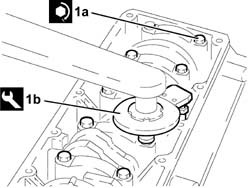
Rotate the crankcase through 180° on the overhaul stand.1. Remove the oil filter (1a) using the tool (1b).2. Undo pin (2a) and remove heat exchanger (2b).
1. Fit the tool. | Description | Code |
|---|
| 1 | Counter-torque | 1.860.846.000 |
1. Undo the bolts (1a) and remove the clutch (1b).
1. Undo the bolts (1a) and remove the crankshaft pulley (1b).2. Remove the timing belt.3. Undo the bolt (left hand thread) (3a) and remove the toothed timing drive pulley (3b).
1. Undo the bolts (1a) and remove the flywheel (1b).2. Remove the tool. | Description | Code |
|---|
| 2 | Counter-torque | 1.860.846.000 |
1. Undo the bolts (1a) and timing side power unit support (1b).2. Undo the bolt (2a) and remove the fixed timing tensioner (2b).3. Undo the bolt (3a) and remove the auxiliary units drive belt automatic belt tensioner (3b).4. Undo the bolts (4a) and remove the support (4b) complete with power assisted steering pump (4c) and timing belt tensioner.
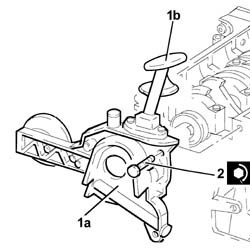
1. Undo the bolts (1a) and remove the crankcase front cover (4b) with the oil pump incorporated (1b) complete with intake (1c).Remove the seal.
Fit the tool. | Description | Code |
|---|
| - | Flange | 1.860.815.000 |
Rotate the crankcase through 180° on the overhaul stand.1. Undo the bolts (1a) and remove the connecting rod cap (1b).2. Remove the lower connecting rod half-bearing.3. Remove the connecting rod-piston assembly.4. Remove the upper connecting rod half-bearing.Carry out the same operations to remove the pistons and connecting rods for the remaining cylinders.Remove the tool. | Description | Code |
|---|
| - | Flange | 1.860.815.000 |
Undo the bolts and remove the flywheel guard.5. Undo the bolts (5a) and remove the crankcase rear cover (5b) with the oil seal incorporated.Check that the crankshaft endfloat corresponds to the recommended figures using a magnetic base and dial gauge. | Measurement | | Value |
|---|
| - | End float (mm) | | 0.049 - 0.211 |
If the value for the crankshaft endfloat does not correspond with the recommended figures, when refitting, regrind the crankcase seat and use suitable oversize thrust washers.6. Undo the bolts (6a) and remove the bearing caps (6b).7. Remove the lower main journal half-bearings.8. Remove the crankshaft.9. Undo the bolts (9a) and remove the crankshaft flywheel (9b).10. Remove the upper main journal half-bearings.11. Remove the thrust washers.12. Undo the bolts (12a) and remove the jets (12b) from the crankcase.13. Undo the bolt (13a) and remove the rpm and timing sensor (13b).14. Remove the engine oil minimum pressure warning light sensor.
1. Undo the bolts (1a) and remove the flange (1b) complete with oil return pipe from the turbocharger.2. Undo the connector (2a) and remove the turbocharger oil supply pipe (2b).3. Undo the bolts (3a) and remove the turbocharger mounting bracket (3b).
Rotate the crankcase through 90° on the overhaul stand.Undo the bolts and remove the crankcase from the mounting brackets, then place it on a special workbench. Op. 1028H60 PISTON SET, GUDGEON PINS AND SEALS - REPLACE WITH PISTONS AND CONNECTING RODS AT THE BENCH - INCLUDES ALIGNMENT AND BALANCING.Undo the bolts and remove the intake duct from the oil pump. Op. 1084B18 ENGINE OIL PUMP, REMOVED - CHECK AT BENCH.
Refitting
(
Removing
)
Wash the dismantled components.Fit the water/oil sealing plugs in the crankcase using suitable fitting tools.Lubricate all the mechanical components with engine oil.Check that the cylinder head support surface does not have cracks or superficial grooves.Check that the planarity of the cylinder head support surface corresponds to the recommended figure; if this is not the case, regrind the cylinder head support surface. | Measurement | | Value |
|---|
| - | Cylinder head support surface flatness (mm) | | < 0.1 |
1. Measure the cylinder bore diameter using the diagram illustrated. | Measurement | | Value |
|---|
| - | Cylinder liner diameter (mm) | Category A | 82.000 - 82.010 |
| Category B | 82.010 - 82.020 |
| Category C | 82.020 - 82.030 |
Check that the taper of the cylinder liners is within the recommended limits. | Measurement | | Value |
|---|
| - | Cylinder liner taper (mm) | | < 0.005 |
Check that the ovality of the cylinder liners is within the recommended limits. | Measurement | | Value |
|---|
| - | Cylinder liner ovality (mm) | | < 0.05 |
If the cylinder bore measurements are not within the recommended limits, ream the cylinder bores following the recommended oversizes. | In the case of reaming, all the bores must have the same oversize. |
| Measurement | | Value |
|---|
| - | Cylinder liner oversize (mm) | | 0.1 |
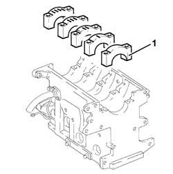
1. Fit the bearing caps. | The bearing caps have progressively numbered references (from zero to four starting from the front of the engine) which define the fitting position. |
1. Tighten the bearing cap bolts (1a) to torque using the angular tightening tool (1b). | Fastening | Component | dia | Value(daNm) |
|---|
| 1a | Bolt | MAIN BEARING CAPS | M12 | 2.4 - 2.6 + 100° |
| Description | Code |
|---|
| 1b | Torque wrench | 1.860.942.000 |
2. Check that the diameter of the main journal seats is within specified limits. | Measurement | | Value |
|---|
| 2 | Main journal seat diameter (mm) | | 63.691 - 63.732 |
Undo the bolts (1a) and remove the connecting rod caps.
Check that there are no deposits or blockages in the crankshaft lubrication ducts.Check that the diameter of the main journals is within specified limits. | Measurement | | Value |
|---|
| - | Main journal diameter (mm) | Category A | 59.994 ÷ 60.000 |
| Category B | 59.987 ÷ 59.993 |
| Category C | 59.982 ÷ 59.986 |
If the diameter of the main journals is not correct, they should be reground to the recommended undersize. | Measurement | | Value |
|---|
| - | Main journal undersize (mm) | | 0.127 |
Check that the diameter of the crankpins corresponds to the recommended figures. | Measurement | | Value |
|---|
| - | Crankpin diameter (mm) | Category A | 50.799 ÷ 50.805 |
| Category B | 50.793 ÷ 50.799 |
| Category C | 50.787 ÷ 50.793 |
If the diameter of the crankpins is not correct, they should be reground to the recommended undersize. | Measurement | | Value |
|---|
| - | Crankpin undersize (mm) | | 0.127 |
Check that the small end bush internal diameter is within the recommended limits; if not, replace the worn small end bush ( ). | Measurement | | Value |
|---|
| - | Inner diameter (mm) | | 26.006 - 26.012 |
Check that the inner diameter of the piston bushes corresponds to the recommended figures; if not, replace the piston complete with piston rings, gudgeon pin and bushes. | Measurement | | Value |
|---|
| - | Piston bush internal diameter (mm) | | 25.999 - 26.004 |
Check that the outer diameter of the gudgeon pins is within the recommended limits; if not, replace the worn gudgeon pins. | Measurement | | Value |
|---|
| - | Outer diameter (mm) | | 25.982 - 25.988 |
Fit the piston rings in the cylinder liner and check that the opening between the ends is within the recommended values; if this is not the case, replace the circlips. | Measurement | | Value |
|---|
| - | Gap (mm) | 1st Ring | 0.25 - 0.40 |
| 2nd ring | 0.25 - 0.50 |
| Oil scaper ring | 0.25 - 0.50 |
Check that the outer diameter of the pistons is within specified limits; if not, replace the piston complete with sealing rings and pin. | Measurement | | Value |
|---|
| - | Outer diameter (mm) (**) | Category A | 81.783 - 81.797 |
| Category B | 81.793 - 81.807 |
| Category C | 81.803 - 81.817 |
| Measure perpendicular to the gudgeon pin axis, 8 mm from the lower edge of the skirt. |
1. Check that the axial clearance (1a) between the second ring (1b) and the housing in the piston (1c) corresponds to the recommeded figure. | Measurement | | Value |
|---|
| 1a | End float (mm) | | 0.002 - 0.006 |
Check that the axial clearance between the oil scraper ring and the housing in the piston corresponds to the recommeded figures. | Measurement | | Value |
|---|
| - | End float (mm) | | 0.030 - 0.065 |
1. Fit the caps (1b) on the connecting rods (1a) and secure them tightening the bolts (1c) to torque. | Fit the connecting rods so that the number stamped on each rod faces toward the same side as the number stamped on the big end (inlet side). |
| Fastening | Component | dia | Value(daNm) |
|---|
| 1c | Bolt | CONNECTING ROD CAPS | M9 | 2.4 - 2.6 + 60° |
2. - Check that the diameter of the big end corresponds to the recommended figures; if not, replace the connecting rods. | Measurement | | Value |
|---|
| 2 | Big end diameter (mm) | | 53.883 ÷ 53.923 |
Op. 1028H60 PISTON SET, GUDGEON PINS AND SEALS - REPLACE WITH PISTONS AND CONNECTING RODS AT THE BENCH - INCLUDES ALIGNMENT AND BALANCING. Op. 1084B18 ENGINE OIL PUMP, REMOVED - CHECK AT BENCH.Fit the intake and secure it to the crankcase front cover using the bolts.Check that there are no signs of seizing on the flywheel ring gear teeth; if this is not the case, replace it.Fit the flywheel guard on the crankcase and tighten the bolts.Fit the crankcase on the overhaul stand and secure it using the bolts.Fit the turbocharger mounting bracket and secure it using the bolts.Fit the oil supply pipe to the turbocharger and tighten the connector.Fit the flange complete with oil return pipe to the sump from the turbocharger and secure it using the bolts.Fit the minimum engine oil pressure warning light sensor and tighten it to torque. | Fastening | Component | dia | Value(daNm) |
|---|
| - | - | INSUFFICIENT ENGINE OIL PRESSURE SWITCH | - | 1.9 - 2.3 |
Fit the rpm and timing sensor and secure it using the bolt.Fit the jets on the crankcase and secure them using the bolts.Fit the flywheel on the crankshaft and secure it using the bolts.Fit the upper main journal half-bearings.Fit the crankshaft in the crankcase.Fit the thrust washers on the third main journal.1. Fit the main bearing caps complete with half-bearings. | The bearing caps have progressively numbered references (from zero to four starting from the front of the engine) and a dot which define the fitting position. |
1. Tighten the bearing cap bolts (1a) to torque using the angular tightening tool (1b). | Fastening | Component | dia | Value(daNm) |
|---|
| 1a | Bolt | MAIN BEARING CAPS | M12 | 2.4 - 2.6 + 100° |
| Description | Code |
|---|
| 1b | Torque wrench | 1.860.942.000 |
1. Fit the tool. | Description | Code |
|---|
| 1 | Flange | 1.860.815.000 |
Rotate the crankshaft using the tool fitted previously until the crankpin for the cylinder concerned is at B.D.C.1. Fit the piston-connecting rod assembly (1a) complete with half-bearing using the tool (1b). | The piston-connecting rod assemblies are fitted in the cylinder block/crankcase so that the piston oil jets are facing the intake side. |
2. Fit the connecting rod cap (2a) complete with half-bearing and secure it without tightening the bolts (2b). | Fit the connecting rods so that the number stamped on each rod faces toward the same side as the number stamped on the big end (inlet side). |
Carry out the same operations to refit the pistons and connecting rods for the remaining cylinders.
1. Tighten the connecting rod cap bolts (1a) to torque using the angular tightening tool (1b). | Place an axial shim between the connecting rod and the crankshaft when tightening the connecting rod cap. |
| Fastening | Component | dia | Value(daNm) |
|---|
| 1a | Bolt | CONNECTING ROD CAPS | M9 | 2.4 - 2.6 + 60° |
| Description | Code |
|---|
| 1b | Torque wrench | 1.860.942.000 |
Remove the tool. | Description | Code |
|---|
| - | Flange | 1.860.815.000 |
1. Fit the crankcase rear cover with built in oil seal.2. Tighten the crankcase rear cover bolts to torque. | Fastening | Component | dia | Value(daNm) |
|---|
| 2 | Bolt | REAR COVER CRANKSHAFT | M6 | 0.8 - 1.0 |
1. Place the crankcase front cover with built-in oil pump (1a) in its housing complete with intake (1b) and gasket2. Tighten the crankcase front cover bolts, complete with oil pump, to torque. | Fastening | Component | dia | Value(daNm) |
|---|
| 2 | Bolt | FRONT COVER CRANKSHAFT | M6 | 0.8 ÷ 1.0 |
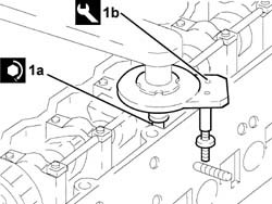
1. Fit the seal (1a) on the oil pump using the tool (1b). | Description | Code |
|---|
| 1b | Fitting tool | 1.860.816.000 |
Apply sealant to the entire perimeter of the crankcase sump. | Type | Component | Description | Qty. |
|---|
| - | Silicon sealant | ENGINE OIL SUMP | - | - |
1. Fit the crankcase sump.2. Tighten the side bolts (2a) fixing the crankcase sump to torque using the tool (2b). | Fastening | Component | dia | Value(daNm) |
|---|
| 2a | Side bolts | ENGINE OIL SUMP | M8 | 2.1 - 2.6 |
| Description | Code |
|---|
| 2b | Spanner | 1.860.834.000 |
3. Tighten the front and rear bolts (3a) crosswise fixing the crankcase sump to torque using the tool (3b). | Fastening | Component | dia | Value(daNm) |
|---|
| 3a | Front and rear bolts | ENGINE OIL SUMP | M6 | 0.7 - 0.9 |
| Description | Code |
|---|
| 3b | Spanner | 1.860.833.000 |
Rotate the engine through 180° on the overhaul stand.1. Fit the tool. | Description | Code |
|---|
| 1 | Counter-torque | 1.860.846.000 |
2. Fit the flywheel (2a) and apply LOCTITE 573 to the bolts (2b) and tighten them to torque. | Fastening | Component | dia | Value(daNm) |
|---|
| 2b | Bolt | FLYWHEEL (MECH.) | M12 | 13.6 - 16.8 |
1. Fit the clutch (1a) and tighten the bolts (1b) to the recommended torque.
1. Fit the toothed drive pulley (1c) and tighten the bolt (left hand thread) (1b) to torque. | Fastening | Component | dia | Value(daNm) |
|---|
| 1b | Left hand bolt | DRIVE PULLEY(PULLIES) TIMING | M16 | 30.6 - 37.8 |
Remove the tool. | Description | Code |
|---|
| - | Counter-torque | 1.860.846.000 |
Fit the power steering pump complete with mounting bracket.Fit the fixed timing system tensioner in its housing and secure it using the bolts.Fit the timing side power unit support.Fit the auxiliary drive belt automatic tensioner and secure it with the bolt.Fit the heat exchanger and secure it using the pin.Fit the oil filter.1. Measure the piston projection in two places at 180° on the gudgeon pin axis using the tool and take the average of the two values measured for each piston. | Description | Code |
|---|
| 1 | Dial gauge support | 1.870.404.000 |
Select the correct size cylinder head gasket depending on the maximum average protrusions for each individual piston. | Measurement | | Value |
|---|
| - | Average maximum piston projection (mm) | | 0.795 - 0.881 |
| (no reference) (mm) | 1.55 - 1.65 |
| Measurement | | Value |
|---|
| - | Average maximum piston projection (mm) | | 0.881 - 0.967 |
| (one reference) (mm) | 1.65 - 1.75 |
| Measurement | | Value |
|---|
| - | Average maximum piston projection (mm) | | 0.967 - 1.055 |
| (two references) (mm) | 1.75 - 1.85 |
Position the cylinder head locating bushes on the engine block.Fit the cylinder head gasket selected. | The cylinder head gasket is ASTADUR type. The material from which the gasket is made undergoes a polymerization process during the operation of the engine so that it becomes considerably harder during usage. |
In order for the polymerization process to take place, it is necessary to:
- keep the gasket sealed in its casing until it is fitted
- not lubricate the gasket or the contact surfaces with oil.
- Position the cylinder head on the cylinder block/crankcase
1. Tighten the cylinder head bolts (1a) to torque using the angular tightening tool (1b).Follow the order shown in the figure for each tightening sequence. | Fastening | Component | dia | Value(daNm) |
|---|
| 1a | Bolt | CYLINDER HEAD | M12 | 6.5 |
| Description | Code |
|---|
| 1b | Torque wrench | 1.860.942.000 |
-
Fit the cam cover complete with gasket and secure it by tightening the bolts to torque. | Fastening | Component | dia | Value(daNm) |
|---|
| - | Bolt | CAM COVER | M6 | 0.8 ÷ 1.0 |
Fit the mounting complete with pressure pump and secure it using the side and front bolts.Fit the power steering pump supply pipe mounting bracket and secure it using the bolts.Connect the pipe and tighten the connector.1. Remove the oil pump bolt shown.Temporarily fit the toothed timing drive belt on the drive pulley.2. Fit the tool. | The crankshaft must be rotated, using small movements, to allow the locating dowel to be fitted on the toothed timing drive pulley. |
| Description | Code |
|---|
| 2 | Template | 1.860.905.000 |
1. Rotate the driven toothed pulley until the timing references are aligned.2. Fully fit the toothed timing drive belt.3. Use a screwdriver in the opening (3a) for leverage until the reference on the tensioner (3b) is aligned with the opening reference (3c) and tighten the belt tensioner nut (3d) to torque in this position. | Fastening | Component | dia | Value(daNm) |
|---|
| 3d | Nut | MOBILE TIMING TENSIONER | M10 | 4.2 - 5.2 |
Remove the tool. | Description | Code |
|---|
| - | Template | 1.860.905.000 |
Rotate the crankshaft through two revolutions.Recheck that the timing references and the tensioning references on the timing belt tensioner are aligned.
Fit the timing belt covers and secure them using the bolts.Fit the power unit reaction rod mounting bracket.Fit the crankshaft pulley and secure it using the bolts.Fit the exhaust manifold gasket.Fit the exhaust manifold, complete with turbocharager and E.G.R. valve and secure it tightening the nuts to torque. | Fastening | Component | dia | Value(daNm) |
|---|
| - | Nut | EXHAUST MANIFOLD/S | M8 | (Cylinder head side) 2.1 - 2.6 |
Fit the coolant manifold and secure it using the bolts.Connect the oil inlet pipe to the turbocharger.Connect the sump oil return pipe to the turbochager.Fit the protection for the oil return pipe to the sump from the turbocharger and secure it using the bolts.Tighten the nut fixing the exhaust manifold to the cylinder block/crankcase.Remove the seal.Connect the exhaust gas recirculation pipe and secure it to the using the nuts.Fit the exhaust gas recirculation pipe heat shield and tighten the bracket bolt.Fit the turbocharger heat shield and secure it using the bolts.Fit the bracket.Fit the oil vapour separator complete with bracket and secure it using the nuts.Connect the condensation oil recovery pipe to the crankcase sump.Connect the engine oil vapour recovery pipe to the crankcase and to the head.Using a fixed spanner, bring the connectors for the pipes from the fuel manifold to the injectors, injector side, in contact, then tighten them to the recommended torque using a suitable fork torque wrench. | Fastening | Component | dia | Value(daNm) |
|---|
| - | Connector | PIPE FUEL MANIFOLD TO INJECTORS | M12 | (Injector side) 2.3 |
Tighten the connectors for the pipes from the fuel manifold to the manifold side injectors to torque using the tool. | Fastening | Component | dia | Value(daNm) |
|---|
| - | Connector | PIPE FUEL MANIFOLD TO INJECTORS | M14 | (Manifold side) 2.3 |
| Description | Code |
|---|
| - | Spanner | 1.852.138.000 |
Fit the diesel supply pressure regulator to the pressure pump and secure it using the bolts.Connect the pipes to the pressure regulator.Fit the oil dipstick assembly and secure it using the bolts.Fit the auxiliary drive belt pulley and secure it using the bolt. Op. 1004D40 ENGINE - POSITION ON STAND AND REMOVE.