2585285 - 1016E10 single cylinder head, removed - overhaul
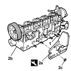
Remove the cylinder head from the vice.Unscrew the bolts and remove the mounting tool.| Description | Code | |
|---|---|---|
| - | Support | 1.860.470.000 |
| Description | Code | |
|---|---|---|
| 2a | Support | 1.860.470.000 |
| Description | Connector | |
|---|---|---|
| 3c | Fuel pressure sensor | See K83 FUEL PRESSURE SENSOR ( ENGINE ) |
| Description | Connector | |
|---|---|---|
| - | Heater plugs | See A040 HEATER PLUGS |


| Description | Code | |
|---|---|---|
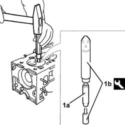
| 1b | Support for counter-torque | 1.860.831.000 |
| Description | Connector | |
|---|---|---|
| 3b | Timing sensor | See K47 TIMING SENSOR ( ENGINE ) |

| Description | Connector | |
|---|---|---|
| 2a | Injector | See N070 INJECTOR |
| Description | Connector | |
|---|---|---|
| 4 | Heater plugs | See A040 HEATER PLUGS |

| Measurement | Value | ||
|---|---|---|---|
| - | End float (mm) | 0.100 - 0.230 |
| When removing, mark the camshaft caps with a progressive number to define their installation position. |
| When removing, mark the cups with a progressive number to define their installation position. |

| Description | Code | |
|---|---|---|
| 1b | Tool | 1.860.644.000 |

| Description | Code | |
|---|---|---|
| 1b | Extractor | 1.860.989.000 |
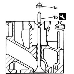
| Mark the valves with a progressive number to define their installation position. |
| Description | Code | |
|---|---|---|
| - | Support | 1.860.470.000 |

| Description | Code | |
|---|---|---|
| 1b | Extractor | 1.860.395.001 |

| Measurement | Value | ||
|---|---|---|---|
| - | Lower plane planarity (mm) | 0.1 |
| Measurement | Value | ||
|---|---|---|---|
| 1 | Minimum permitted height (mm) | 140.6 |

| Measurement | Value | ||
|---|---|---|---|
| - | Stem diameter (mm) | 7.974 - 7.992 |
| Measurement | Value | ||
|---|---|---|---|
| - | Outer diameter (mm) | 36.975 - 36.995 |
| Measurement | Value | ||
|---|---|---|---|
| - | Cup housing diameter (mm) | 37.000 - 37.025 |
| Measurement | Value | ||
|---|---|---|---|
| - | Free length (mm) | 53.9 |
| Measurement | Value | ||
|---|---|---|---|
| - | Length (mm) | 36 | |
| under a load of (daN) | 36.7 - 39.6 | ||
| Measurement | Value | ||
|---|---|---|---|
| - | Length (mm) | 26.5 | |
| under a load of (daN) | 56.0 - 61.0 | ||
| Measurement | Value | ||
|---|---|---|---|
| - | Journal diameter (mm) | 26.000 - 26.015 |
| Measurement | Value | ||
|---|---|---|---|
| - | Nominal cam height (mm) | 8.5 |
| Fastening | Component | dia | Value(daNm) | |
|---|---|---|---|---|
| 1b | Bolt | CAMSHAFT CAPS | M7 | 1.3 - 1.6 |
| Measurement | Value | ||
|---|---|---|---|
| 2 | Diameter (mm) | 26.045 - 26.070 |

| Measurement | Value | ||
|---|---|---|---|
| - | Outer diameter (mm) | 14.010 ÷ 14.030 | |
| Oversizes (mm) | 0.05, 0.10, 0.25 | ||
| The valve guides should be fitted after the cylinder head has been heated to a temperature of 80° - 100°C. |
| Description | Code | |
|---|---|---|
| 1b | Fitting tool | 1.860.812.000 |
| Measurement | Value | ||
|---|---|---|---|
| - | Inner diameter (mm) | 8.022 ÷ 8.040 |

| Measurement | Value | ||
|---|---|---|---|
| - | Upper ring taper (mm) | "a" | 70° |
| Measurement | Value | ||
|---|---|---|---|
| - | Width of ring in contact with valve (mm) | "b" | 45° +- 5'' |
| Measurement | Value | ||
|---|---|---|---|
| - | Lower ring taper (mm) | "c" | 15° |
| Measurement | Value | ||
|---|---|---|---|
| - | Width of band in contact with valve (mm) | " I " | +- 2 |

| Measurement | Value | ||
|---|---|---|---|
| 1 | Cylinder head plane recess (mm) | 0.1 - 0.5 |
| Description | Code | |
|---|---|---|
| 1 | Dial gauge support | 1.870.404.000 |

| Description | Code | |
|---|---|---|
| 1b | Drift | 1.860.814.000 |
| Description | Code | |
|---|---|---|
| 1b | Fitting tool | 1.860.313.000 |
| Description | Code | |
|---|---|---|
| 1c | Drift | 1.867.019.000 |

| Description | Code | |
|---|---|---|
| 1b | Tool | 1.860.644.000 |

| Apply LOCTITE 573 to the contact surfaces with the head for the 1st and 5th camshaft caps. |
| Fastening | Component | dia | Value(daNm) | |
|---|---|---|---|---|
| 2 | Bolt | CAMSHAFT CAPS | M7 | 1.3 - 1.6 |

| Description | Code | |
|---|---|---|
| 1b | Fitting tool | 1.860.824.000 |
| Description | Connector | |
|---|---|---|
| 2 | Heater plugs | See A040 HEATER PLUGS |
| Fastening | Component | dia | Value(daNm) | |
|---|---|---|---|---|
| 2 | - | GLOW PLUGS | M12 | 1.3 - 1.6 |

| Description | Connector | |
|---|---|---|
| 2a | Injector | See N070 INJECTOR |
| Fastening | Component | dia | Value(daNm) | |
|---|---|---|---|---|
| 3b | Nut | INJECTORS(DIESEL) | M8 | 2.6 - 3.2 |

| Fastening | Component | dia | Value(daNm) | |
|---|---|---|---|---|
| 1c | Bolt | COOLANT PUMP | M8 | 2.5 |
| Description | Connector | |
|---|---|---|
| 2a | Timing sensor | See K47 TIMING SENSOR ( ENGINE ) |
| Fastening | Component | dia | Value(daNm) | |
|---|---|---|---|---|
| 4a | Bolt | TIMING DRIVEN PULLEY | M12 | 10.2 - 12.6 |
| Description | Code | |
|---|---|---|
| 4b | Support for counter-torque | 1.860.831.000 |

| Measurement | Value | ||
|---|---|---|---|
| - | Inlet valve clearance in closed position (mm) | Inlet | 0.25 - 0.35 |
| Exhaust | 0.30 - 0.40 | ||
| Description | Code | |
|---|---|---|
| 1 | Lever | 1.860.443.000 |
| Description | Code | |
|---|---|---|
| 2 | Lever | 1.860.724.000 |
| Description | Code | |
|---|---|---|
| - | Lever | 1.860.443.000 |
| Description | Code | |
|---|---|---|
| - | Lever | 1.860.724.000 |

| Fastening | Component | dia | Value(daNm) | |
|---|---|---|---|---|
| - | Bolt | COOLANT PUMP PULLEY | M8 | 2.5 |
| Fastening | Component | dia | Value(daNm) | |
|---|---|---|---|---|
| 3b | Bolt | VACUUM PUMP FOR BRAKES | M8 | 2.5 |

| Fastening | Component | dia | Value(daNm) | |
|---|---|---|---|---|
| 2a | Pin | THERMOSTAT | M8 | (Cylinder head side) 2.3 - 2.8 |
| Fastening | Component | dia | Value(daNm) | |
|---|---|---|---|---|
| 2b | Bolt | THERMOSTAT | M8 | (Cylinder head side) 2.3 - 2.8 |

| Fastening | Component | dia | Value(daNm) | |
|---|---|---|---|---|
| 1c | - | - | - | - |

| Description | Connector | |
|---|---|---|
| - | Heater plugs | See A040 HEATER PLUGS |
| Description | Connector | |
|---|---|---|
| - | Fuel pressure sensor | See K83 FUEL PRESSURE SENSOR ( ENGINE ) |
| Fastening | Component | dia | Value(daNm) | |
|---|---|---|---|---|
| 4 | Connector | PIPE FUEL MANIFOLD TO INJECTORS | M12 | (injector side) 2.3 |
| Fastening | Component | dia | Value(daNm) | |
|---|---|---|---|---|
| 5a | Connector | PIPE FUEL MANIFOLD TO INJECTORS | M14 | (Manifold side) 2.3 |
| Description | Code | |
|---|---|---|
| 5b | Spanner | 1.852.138.000 |

| Description | Code | |
|---|---|---|
| - | Support | 1.860.470.000 |