2585406 - Introduction - BRAKING SYSTEM
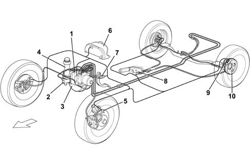
The vehicle is fitted with self-ventilated front disc brakes with floating calipers and rear drum brakes with self-centring shoes and automatic recovery of the clearance. The braking system is operated by a pedal with a 10'' vacuum brake servo for the 1242 engine and a 9'' vacuum servo for the 1910D version, both combined with a 7/8'' master cylinder. The hydraulic system is the split type with two independent crossover circuits with a load proportioning valve on the rear brake circuit (versions without ABS).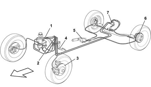
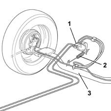
LOAD PROPORTIONING VALVE
On versions without ABS, a load proportioning valve is fitted to distribute braking action over the front and rear wheels as effectively as possible.The device reduces pressure in the rear drum brake control cylinders by an amount proportional to the static load acting on the rear axle and according to the dynamic load acting on the wheels of the axle.Device (1) secured to the vehicle floor pan is connected via a spring (2) to the rear axle (3).The aim of the device is to prevent the rear wheels locking (due to excessive braking action) when the vehicle is low and also to ensure that the braking action increases to allow the vehicle to brake under higher load conditions.Under conditions of high static load (laden car), the load proportioning valve acts to maximum effect, i.e. the device allows more fluid to pass through it and thus an increased braking action. With a low static load, on the other hand, axle movement during car motion triggers release of the return link and thus reduces braking action.| If replaced, the part should be installed in accordance with installation procedures shown in the removal and refitting procedure. |
| If the spring becomes separated from the load proportioning valve as a result of maintenance operations on the rear axle, it should be refitted as described in the removal/refitting procedure. |
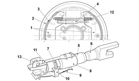
REAR SHOE-DRUM AUTOMATIC PLAY TAKE-UP DEVICE
Play between shoes (1) and rear drum (2) due to wear on lining (3) is taken up automatically by a mechanical device (4).The device consists of a link in two parts. The forked ends of the parts are held in contact with the brake shoes by a spring inside the device.The automatic adjustment system is operational during service brake operation and also during parking brake operation because the parking brake mechanism is also in contact with the rear adjustment device fork.Both parts of the device are joined together by an interior worm screw system. An external toothed lock-ring (6) is in contact with a ratchet integral with the spring.The device works on the principle that it extends during braking and then stays long enough to take up the clearance due to wear on the friction material.When the brake shoes widen during braking, spring action allows the link to extend by unscrewing the worm screw system.If the extending link causes the outer lock-ring to turn so much that it causes the ratchet to click, it is impossible for both parts of the device to come together again during the successive brake release stage.A thermal clip (6) is also present to allow the device to operate properly if the rear brakes overheat. The heat-sensitive clilp blocks the operation of the autoamtic play take-up device if the brake shoes expand because otherwise the brakes would lock when the shoes cooled down.If the brake shoes are replaced, the device is adjusted by means of lock-ring (5) until it fits the new shoes.