244000436 - CONNECT
Connect is the infotelematic system fitted to this vehicle. It interacts with the user to facilitate driving and make life inside the passenger compartment as pleasant as possible.The Connect system is not fitted to the vehicle as standard but is available as an option.COMPOSITION
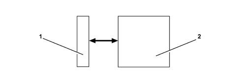
System architecture
The Connect system consists of:- FRONT PANEL (1), which acts as the physical interface between system and user. It incorporates a display, a numerical keypad and function keys.
- SILVER BOX (2), containing the motherboard, radio module, GSM module and Audio CD player/CD ROM drive
Connect configurations
The Connect system is also available in the following configurations: LEVEL 1 (L1), LEVEL 2 (L2), LEVEL 3 (L3), LEVEL 4 (L4).L1, includes the following modules:- Radio
- CD player
- GSM Module
- GPS Module
- Assistance services
- 192x80 pixel LCD graphic display
- External CD CHANGER system (if present)
- Options: WAP protocol + MP3
- Radio
- CD player
- GPS Module
- Independent navigation with pictograms
- 192x80 pixel LCD graphic display
- External CD CHANGER system (if present)
- Radio
- CD player
- GPS Module
- GSM Module
- Independent navigation with pictograms
- Targasys Services
- 192x80 pixel LCD graphic display
- External CD CHANGER system (if present)
- Options: WAP protocol + MP3
- Radio
- CD player
- GPS Module
- GSM Module
- Independent navigation with maps
- Targasys Services
- 5" TFT (Thin Film Transistor) display
- Options: Telepass information display (if present), external CD CHANGER system (if present), built-in voice recognition module, MP3
Description of internal modules
Various different modules make up the system for providing services or obtaining information.CD player
The CD drive can read the and manage the audio CD to play music CDs and read CD ROMs.Connect is also designed to be connected to an external CD Changer and to accept analogue audio output. The device for which it is designed as a Blaupunkt CD changer.The CD Changer is not supplied as standard with the Connect system.GSM phone
Connect L1 and L4 are equipped with a Dual Band module and Sim Card reader (that allows the user the insert a SIM Card).The SIM reader is designed for an ISO format SIM Card.A plug-in format Sim Card can be used only with an ISO adaptor.Radio module
The module comprises:- Tuner
- Audio power amplifier
- Control software
- Interface for external CD changer
- Interface for external audio inputs
- Phone audio (analogue - mono)
- Navigator audio (analogue - mono)
- CD-DA audio player inside Connect
- Audio for CD-Changer external to Connect (analogue - stereo [from ISO connector])
- Output with 4 amplified analogue audio channels.
- Preparation for interface with BOSE system.
Description of controls
The Connect front panel, shown in the following figure (Fig. 2), houses the keys that allow the user to control the system.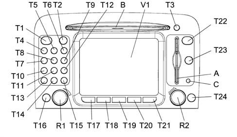
| Key | Short press on key (less than 1 second) | Long press on key (more than 1 second) |
|---|---|---|
| T4 - T5 - T6 - T7 - T8 - T9 | Numbers "1", "2", "3", "4", "5", "6" on phone keypad. Stored station recall | Storing station nos. 1-2-3-4-5-6 |
| T10 | Number 7 on phone keypad. Select previous CD on CD-Changer (if installed) | - |
| T11 | Number 8 on phone keypad | - |
| T12 | Number 9 on phone keypad. Select next CD on CD-Changer (if installed) | - |
| T14 | Number 0 on phone keypad. Audio CD Play/Stop | Audio CD play pause |
| T13 | (*) symbol on phone keypad. Radio mode: search for first available station with lower frequency. CD mode: select previous track | - |
| T15 | (#) symbol on phone keypad. Radio mode: search for first available station with higher frequency. CD mode: select next track | - |
| T1 | Send phone cal Accept incoming call End current phone call | Refuse incoming phone call |
| T2 | Activate/deactivate voice recognition | Store voice command |
| T16 | Select operating mode: FM1-FM2-FM3-LW-MW-CD-CDC(if installed) | - |
| R1 | This knob is known as an encoder. Turn system on/off (press knob). Adjust volume (turn knob) | - |
| T17 MAIN/DARK | Select main screen | Darken monitor (stand-by) |
| T18 AUDIO/OFF | Select radio screen. Turn on radio | Turn of radio |
| T19 TEL/OFF | Select phone screen. Activate phone function | Deactivate phone function |
| T20 NAV/MUTE | Select navigation function | Exclude navigation voice messages (NAV/MUTE function) Reset voice messages |
| T21 TRIP | Select on-board computer screen | - |
| R2 | This knob is known as an encoder. Select function (turn knob). Confirm selected function (pres knob). Activate drop-down menu (press knob with MAIN screen) | - |
| T24 ESC | Exit selected screen. Return to next menu level up and cancel unconfirmed functions | - |
| T23 RPT | Repeat last navigation voice instruction | - |
| T22 Connect | Display emergency or assistance call menu | - |
| T3 | Eject navigation CD-ROM or audio CD | - |
| B | SIM phone card slot | - |
| A | Navigation or Audio CD slot | - |
| C | - Optical sensor for automatic switching of display lighting between night and day settings. |
Interfaces
CD Charger
CONNECT all levels) is also designed to be connected to an external CD Changer and to accept analogue audio output.The interface consists of:- 3-wire stereo analogue input (right, left, reference)
- 2-wire serial control (Rx, Tx)
- Activation signal (Vswitched)
- Permanent power source (Vbatt, GND)
HI-FI system
The CONNECT system is designed to interface with the hi-fi system.The interface consists of:Interface with CAN network (Option)
The CONNECT system is designed to interface components with a CAN bus.Video input
CONNECT is designed to interface with an external video source (parking TV camera) so that it can show imagines on the displayThe interface is an NTSC-format composite video type.Two pins of the MQS connector are dedicated to this interface. These are connected to the video signal and reference (cable and shield).PC interface
CONNECT is designed to interface with a PC via a RS232 serial port.Connect Electrical Absorptions
CONNECT power uptakes during the possible operating modes are as follows:- CONNECT OFF: Imax = 3.2 mA / 13.5V
- CONNECT Stand-By: Imax = 1A / 13.5V
- CONNECT ON: 1.2A / 13.5V %lt; I %lt; 7A / 13.5V
- Screen off, GSM on, radio off: 1.2A / 13.5V
- Screen on, GSM on, radio off: 2A / 13.5V
- Contribution of radio on: 5A / 13.5V
Connectors
Connector arrangement
The arrangement of connectors on the rear of Connect is shown below.
PIN OUT
Connect connector pin-out.
| Pin | Function |
|---|---|
| 1 | n.c. |
| 2 | n.u. |
| 3 | n.c. |
| 4 | Key on input (+Key) |
| 5 | 12 V for aerial amplifier |
| 6 | n.c. |
| 7 | 12 V permanent |
| 8 | Power supply GND |
| Pin | Function |
|---|---|
| 1 | + RH rear speaker |
| 2 | - RH rear speaker |
| 3 | + RH front speaker |
| 4 | - RH front speaker |
| 5 | + LH front speaker |
| 6 | - LH front speaker |
| 7 | + LH rear speaker |
| 8 | - LH rear speaker |
| Pin | Function |
|---|---|
| 1 | n.c. |
| 2 | n.c. |
| 3 | n.c. |
| 4 | n.c. |
| 5 | n.c. |
| 6 | n.c. |
| 7 | Tx [serial RS232] |
| 8 | Rx [serial RS232] |
| 9 | n.c. |
| 10 | Input 1 for Keys on Steering wheel |
| 11 | Input 2 for Keys on Steering wheel |
| 12 | Steering wheel Key reference |
| 13 | n.u. |
| 14 | n.u. |
| 15 | n.u. |
| 16 | n.u. |
| 17 | n.u. |
| 18 | n.u. |
| 19 | n.u. |
| 20 | n.u. |
| Pin | Function |
|---|---|
| 1 | DCD [serial RS232] |
| 2 | Telepass serial |
| 3 | Reversing Signal Input |
| 4 | Composite video earth screen |
| 5 | Composite vide |
| ... DATA ERROR - CROPPED TEXT | Ошибка данных - Текст обрезан ... |
|---|