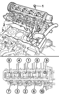
244000643 - 1016C10 SINGLE CYLINDER HEAD, REMOVED - OVERHAUL


| Description | Connector | |
|---|---|---|
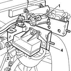
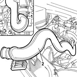
| 1 | Heater plugs control unit | M015C |
| Description | Connector | |
|---|---|---|
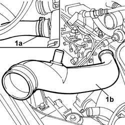
| 1a | EGR solenoid valve | L030 |
| Description | Connector | |
|---|---|---|
| 1b | Throttle body solenoid valve | L062 |

| Description | Connector | |
|---|---|---|
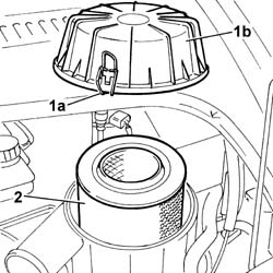
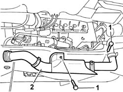
| 1 | Air flow meter | K041 |

| Description | Connector | |
|---|---|---|
| 1b | Oil vapour heating resistance | O007A |

| Description | Connector | |
|---|---|---|
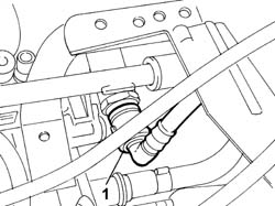
| 1b | Heater plugs | A040 |

| Description | Connector | |
|---|---|---|
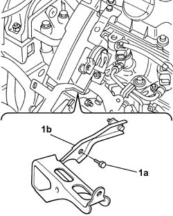
| 1a | Injection pump third piston deactivation solenoid valve | L005 |
| Description | Connector | |
|---|---|---|
| 1b | Fuel pressure regulator | N077 |
| Description | Connector | |
|---|---|---|
| . | Fuel pressure sensor | K083 |
| Description | Connector | |
|---|---|---|
| 1c | Injector | N070A |
| Description | Connector | |
|---|---|---|
| 1c | Injector | N070B |
| Description | Connector | |
|---|---|---|
| 1c | Injector | N070C |
| Description | Connector | |
|---|---|---|
| 1c | Injector | N070D |
| Description | Connector | |
|---|---|---|
| 1d | Timing sensor | K047 |
| Description | Connector | |
|---|---|---|
| . | Engine oil pressure sensor | K028 |
| Description | Connector | |
|---|---|---|
| 1e | Alternator | A010A |
| Description | Connector | |
|---|---|---|
| 1e | Alternator | A010B |
| Description | Connector | |
|---|---|---|
| 1f | Rpm sensor | K046 |
| Description | Connector | |
|---|---|---|
| 1g | Engine coolant temperature sensor/sender unit | K036 |
| Description | Connector | |
|---|---|---|
| . | Starter motor | A020A |
| Description | Connector | |
|---|---|---|
| . | Starter motor | A020B |


| Description | Code | Function | |
|---|---|---|---|
| . | Spanner | 1.881.138.000 | cylinder head - r + r and replace gasket |

| Description | Code | Function | |
|---|---|---|---|
| . | Spanner | 1.881.138.000 | cylinder head - r + r and replace gasket |


| Description | Code | Function | |
|---|---|---|---|
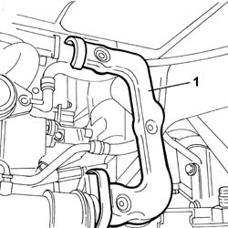
| 1 | Crossmember | 1.870.735.000 | Lower engine mounting beam |

| Description | Connector | |
|---|---|---|
| . | Rpm sensor | K046 |

| Description | Code | Function | |
|---|---|---|---|
| 1 | Flywheel lock | 1.870.765.001 | Prevent flywheel rotation |


| Description | Code | Function | |
|---|---|---|---|
| . | Flywheel lock | 1.870.765.001 | Prevent flywheel rotation |


| Description | Code | Function | |
|---|---|---|---|
| 1 | Pin | 1.860.863.000 | Positioning engine at TDC |
| The pin must be able to enter the hole on the head without the need to turn the crankshaft. If the pulley hole is in the diametrically opposite position, withdraw the TDC tool and turn the crankshaft through one revolution. Then re-fit the TDC tool and then insert the timing adjustment tool. |


| Description | Code | Function | |
|---|---|---|---|
| 1b | Dial gauge support | 1.870.404.000 | Injector projection from cylinder head plane measurement |

| the difference between the minimum and maximum values should not be more than 0.07 mm. |
| Subject | Value | |
|---|---|---|
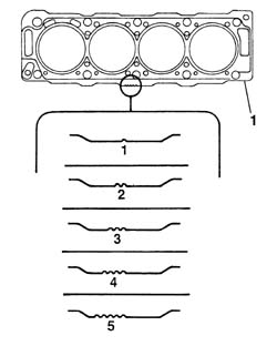
| 1 | CYLINDER HEAD GASKET | mm |
| - | Size | 1,30 |
| - | Average protrusion | 0,470 - 0,605 |
| Subject | Value | |
|---|---|---|
| 1 | CYLINDER HEAD GASKET | mm |
| - | Size | 1,35 |
| - | Average protrusion | 0,605 - 0,655 |
| Subject | Value | |
|---|---|---|
| 1 | CYLINDER HEAD GASKET | mm |
| - | Size | 1,40 |
| - | Average protrusion | 0,655 - 0,705 |
| Subject | Value | |
|---|---|---|
| 1 | CYLINDER HEAD GASKET | mm |
| - | Size | 1,45 |
| - | Average protrusion | 0,705 - 0,755 |
| Subject | Value | |
|---|---|---|
| 1 | CYLINDER HEAD GASKET | mm |
| - | Size | 1,50 |
| - | Average protrusion | 0,755 - 0,830 |
| Value - daNm | Fastening | Component | Ø | |
|---|---|---|---|---|
| . | 2+6+220° | Bolts | CYLINDER HEAD | - |
| Description | Code | Function | |
|---|---|---|---|
| . | Torque wrench | 1.860.942.000 | Connecting rod cap bolt tightening |

| Value - daNm | Fastening | Component | Ø | |
|---|---|---|---|---|
| . | 1,0 | Bolt | CAM COVER | - |

| Subject | Value | |
|---|---|---|
| . | Timing belt/s | unità seem |
| - | Timing belt tension | 108 |

| Description | Code | Function | |
|---|---|---|---|
| . | Pin | 1.860.863.000 | Crankshaft TDC reference |
| Subject | Value | |
|---|---|---|
| . | Timing belt/s | unità seem |
| - | Timing belt tension | 54 |

| Subject | Value | |
|---|---|---|
| . | Timing belt/s | unità seem |
| - | Timing belt tension | 51 - 57 |
| Description | Code | Function | |
|---|---|---|---|
| . | Pin | 1.860.863.000 | Crankshaft TDC reference |
| Description | Code | Function | |
|---|---|---|---|
| . | Pin | 1.860.863.000 | Crankshaft TDC reference |
| Description | Code | Function | |
|---|---|---|---|
| . | Pin | 1.860.863.000 | Crankshaft TDC reference |
| Value - daNm | Fastening | Component | Ø | |
|---|---|---|---|---|
| . | 2,0 | Bolt | TIMING DRIVEN PULLIES | - |
| Value - daNm | Fastening | Component | Ø | |
|---|---|---|---|---|
| . | 2,3 | Bolt | MOBILE TIMING TENSIONER | - |
| Value - daNm | Fastening | Component | Ø | |
|---|---|---|---|---|
| . | (body block) 5 | Nuts | FRONT FLEXIBLE MOUNTING BLOCKS, POWER UNIT | M10 |
| Value - daNm | Fastening | Component | Ø | |
|---|---|---|---|---|
| . | (Rigid mount on engine) 5 | Bolt | FRONT FLEXIBLE MOUNTING BLOCKS, POWER UNIT | M10 |
| Value - daNm | Fastening | Component | Ø | |
|---|---|---|---|---|
| . | (Rigid mount on engine) 8 | Nut | FRONT FLEXIBLE MOUNTING BLOCKS, POWER UNIT | M12 |
| Description | Code | Function | |
|---|---|---|---|
| . | Flywheel lock | 1.870.765.001 | Prevent flywheel rotation |
| Value - daNm | Fastening | Component | Ø | |
|---|---|---|---|---|
| . | 4+51° | Bolt | CRANKSHAFT PULLEY | - |
| Description | Code | Function | |
|---|---|---|---|
| . | Torque wrench | 1.860.942.000 | Connecting rod cap bolt angular tightening |
| Description | Code | Function | |
|---|---|---|---|
| . | Counter-torque | 1.860.765.001 | Loosen/tighten toothed timing drive pulley bolt |
| Description | Connector | |
|---|---|---|
| . | Rpm sensor | K046 |
| Description | Code | Function | |
|---|---|---|---|
| . | Crossmember | 1.870.735.000 | Lower engine mounting beam |
| Value - daNm | Fastening | Component | Ø | |
|---|---|---|---|---|
| . | 2,3 | Bolt | INLET MANIFOLD | - |
| Value - daNm | Fastening | Component | Ø | |
|---|---|---|---|---|
| . | 2,0 | Nut | EXHAUST MANIFOLD/S | - |
| Each time work is carried out on the pipe from the pressure pump to the fuel manifold it must be replaced with a new one to prevent fuel leaks from the connectors. |
| Value - daNm | Fastening | Component | Ø | |
|---|---|---|---|---|
| . | 2 | Connector | PRESSURE PUMP LINE TO FUEL MANIFOLD | - |
| Description | Connector | |
|---|---|---|
| . | Injection pump third piston deactivation solenoid valve | L005 |
| Description | Connector | |
|---|---|---|
| . | Fuel pressure regulator | N077 |
| Description | Connector | |
|---|---|---|
| . | Fuel pressure sensor | K083 |
| Description | Connector | |
|---|---|---|
| . | Injector | N070A |
| Description | Connector | |
|---|---|---|
| . | Injector | N070B |
| Description | Connector | |
|---|---|---|
| . | Injector | N070C |
| Description | Connector | |
|---|---|---|
| . | Injector | N070D |
| Description | Connector | |
|---|---|---|
| . | Timing sensor | K047 |
| Description | Connector | |
|---|---|---|
| . | Engine oil pressure sensor | K028 |
| Description | Connector | |
|---|---|---|
| . | Alternator | A010A |
| Description | Connector | |
|---|---|---|
| . | Alternator | A010B |
| Description | Connector |
|---|
| ... DATA ERROR - CROPPED TEXT | Ошибка данных - Текст обрезан ... |
|---|