244000645 - 1016E10 SINGLE CYLINDER HEAD, REMOVED - OVERHAUL
| Description | Code | Function | |
|---|---|---|---|
| 1 | Support | 1.860.470.000 | Cylinder head in vice |

| Description | Code | Function | |
|---|---|---|---|
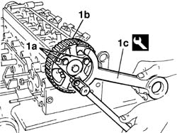
| 1c | Counter-torque | 1.860.776.000 | Timing pulley lock |
| Description | Code | Function | |
|---|---|---|---|
| 1c | Counter-torque | 1.860.776.000 | Timing pulley lock |


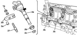
| If the injector is difficult to remove, after removing bracket (2d), remove stud (2f) using a counternut, then use a wrench at the point indicated to shift the injector from its seat. |


| Mark each rocker-tappet pair to allow correct assembly. |

| Description | Code | Function | |
|---|---|---|---|
| 1 | Valve retaining base | 1.860.804.000 | Valve retention |
| Description | Code | Function | |
|---|---|---|---|
| 2b | Tool | 1.860.644.000 | Removing/refitting valves |
| Description | Code | Function | |
|---|---|---|---|
| 2b | Tool | 1.860.877.000 | Removing/refitting valves |
| Description | Code | Function | |
|---|---|---|---|
| . | Valve retaining base | 1.860.804.000 | Valve retention |
| Mark each valve and associated components to allow correct fitting. |

| Description | Code | Function | |
|---|---|---|---|
| 1b | Extractor | 1.860.989.000 | Valve guide oil seal extraction |


| Description | Code | Function | |
|---|---|---|---|
| 1 | Extractor | 1.860.939.000 | Valve guide extraction |

| Description | Code | Function | |
|---|---|---|---|
| . | Support | 1.860.470.000 | Cylinder head in vice |
| Subject | Value | |
|---|---|---|
| 1 | CYLINDER HEAD | mm |
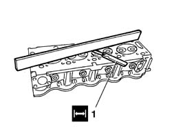
| - | Flatness | 0,05 |
| Subject | Value | |
|---|---|---|
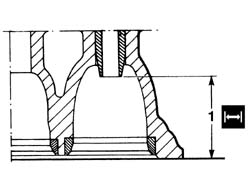
| 1 | CYLINDER HEAD | mm |
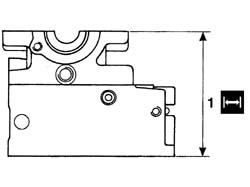
| - | Height | 132,95 - 133,05 |
| Subject | Value | |
|---|---|---|
| . | CYLINDER HEAD | mm |
| - | Minimum permitted height | 132,55 - 132,65 |
| If the height is lower than the minimum level, the cylinder head must be replaced. |
| Subject | Value | |
|---|---|---|
| 1a | VALVE SEATS | |
| - | Contact band angle with intake valve | 45° |
| Subject | Value | |
|---|---|---|
| 1b | VALVE SEATS | |
| - | Intake port outlet angle | 65° |
| Subject | Value | |
|---|---|---|
| 1c | VALVE SEATS | |
| - | Intake port intake angle | 25° |
| Subject | Value | |
|---|---|---|
| 2a | VALVE SEATS | |
| - | Contact band angle with intake valve | 45° |
| Subject | Value | |
|---|---|---|
| 2b | VALVE SEATS | |
| - | Exhaust port intake angle | 25° |
| Subject | Value | |
|---|---|---|
| . | VALVE SEATS | mm |
| - | Intake valve contact band width | 1,00 |
| Subject | Value | |
|---|---|---|
| . | VALVE SEATS | mm |
| - | Exhaust valve contact band width | 2,25 |


| Subject | Value | |
|---|---|---|
| . | VALVE GUIDES | mm |
| - | Oversize valve guide seat diameter | 12,398 - 12,521 |
| Description | Code | Function | |
|---|---|---|---|
| 1b | Fitting tool | 1.870.768.000 | Valve guide fitting |
| It is advisable to heat the cylinder head to 80-100°C to facilitate fitting. |

| Subject | Value | |
|---|---|---|
| 1 | VALVE GUIDES | mm |
| - | Distance between valve guide - lower cylinder head surface | 34,50 - 35,50 |
| Subject | Value | |
|---|---|---|
| 1a | INLET VALVES | mm |
| - | Stem diameter | 5,971 - 5,985 |
| Subject | Value | |
|---|---|---|
| 1b | INLET VALVES | mm |
| - | Head diameter | 35,5 - 35,7 |
| Subject | Value | |
|---|---|---|
| 1c | INLET VALVES | mm |
| - | Height | 106,78 - 107,18 |
| Subject | Value | |
|---|---|---|
| 1d | INLET VALVES | mm |
| - | Contact angle | 45° - 45° 7'30" |
| Subject | Value | |
|---|---|---|
| 1a | EXHAUST VALVES | mm |
| - | Stem diameter | 5,961 - 5,975 |
| Subject | Value | |
|---|---|---|
| 1b | EXHAUST VALVES | mm |
| - | Head diameter | 33,7 - 33,9 |
| Subject | Value | |
|---|---|---|
| 1c | EXHAUST VALVES | mm |
| - | Height | 107,18 - 106,78 |
| Subject | Value | |
|---|---|---|
| 1d | EXHAUST VALVES | mm |
| - | Contact angle | 45° - 45°7'30" |

| Description | Code | Function | |
|---|---|---|---|
| 1b | Dial gauge support | 1.870.404.000 | Injector projection from cylinder head plane measurement |
| Make four diametrically opposed measurements and use the average reading. |
| Subject | Value | |
|---|---|---|
| . | CYLINDER HEAD VALVES (ALL) | mm |
| - | Protrusion from lower cylinder head surface | 0,20 |

| Description | Code | Function | |
|---|---|---|---|
| 1a | Lever | 1.860.490.000 | Valve leakage test |
| Description | Code | Function | |
|---|---|---|---|
| 1b | Sealing pad with pressure gauge | 1.895.868.000 | Valve leakage test |

| Subject | Value | |
|---|---|---|
| . | EXTERNAL VALVE SPRING | |
| - | Length | 37,0 mm |
| - | Under a load of | 24,700-27,300 daN |
| Subject | Value | |
|---|---|---|
| . | EXTERNAL VALVE SPRING | |
| - | Length | 27,7 mm |
| - | Under a load of | 43,225-47,775 daN |
| Value - daNm | Fastening | Component | Ø | |
|---|---|---|---|---|
| . | 1,0 | Bolt | CYLINDER HEAD EXTENSION FASTENERS | - |
| Subject | Value | |
|---|---|---|
| 1 | CAMSHAFT INTAKE AND EXHAUST | mm |
| - | End float | 0,08 - 0,38 |

| Description | Code | Function | |
|---|---|---|---|
| . | Support | 1.860.470.000 | Cylinder head in vice |
| Description | Code | Function | |
|---|---|---|---|
| 2 | Valve retaining base | 1.860.804.000 | Valve retention |

| Description | Code | Function | |
|---|---|---|---|
| 1b | Fitting tool | 1.860.993.000 | Fitting oil seals on valve stems |

| Description | Code | Function | |
|---|---|---|---|
| 2b | Tool | 1.860.644.000 | Removing/refitting valves |
| Description | Code | Function | |
|---|---|---|---|
| 2b | Tool | 1.860.877.000 | Removing/refitting valves |

| Description | Qty. | Component | Type | Classification | |
|---|---|---|---|---|---|
| . | DOW CORNING, 7091 | - | CYLINDER HEAD EXTENSION | Silicone sealant | - |

| Value - daNm | Fastening | Component | Ø | |
|---|---|---|---|---|
| 1 | 1,0 | Bolt | CYLINDER HEAD EXTENSION FASTENERS | - |
| Value - daNm | Fastening | Component | Ø | |
|---|---|---|---|---|
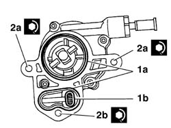
| 2a | 4,3 | Bolt | BRAKING SYSTEM BRAKES | - |
| Value - daNm | Fastening | Component | Ø | |
|---|---|---|---|---|
| 2b | 4,3 | Nut | BRAKING SYSTEM BRAKES | - |
| Description | Code | Function | |
|---|---|---|---|
| 1b | Fitting tool | 1.860.990.000 | Camshaft front oil seal |

| Description | Code | Function | |
|---|---|---|---|
| . | Counter-torque | 1.860.776.000 | Timing pulley lock |
| Value - daNm | Fastening | Component | Ø | |
|---|---|---|---|---|
| . | 4,3 | Nut | TIMING PULLEY FLANGE | - |
| Value - daNm | Fastening | Component | Ø | |
|---|---|---|---|---|
| 1a | 2,3 | Spark plug | GLOW PLUGS | - |
| Value - daNm | Fastening | Component | Ø | |
|---|---|---|---|---|
| 3c | 2,3 | Nut | INJECTORS(DIESEL) | - |
