In operational terms, the fuel supply circuit is divided into a low pressure circuit and a high pressure circuit.The low pressure circuit consists of the tank, auxiliary electric pump submerged in the tank, fuel cooling coil and a return manifold.The high pressure circuit consists of a radialjet pressure pump, outlet manifold and injectors.
Submerged pump assembly (Auxiliary) and fuel level gauge control
The assembly consists mainly of:
a roller-type fuel pump;
a fuel level gauge;
a fuel filter.
The electric pump submerged in the fuel is volumetric roller type with brush motor and permanent magnet excitation.Impeller (1) is turned by the electric motor to create volumes (2) that migrate from intake port (3) to outlet port (4).These volumes are delimited by rollers (5) that adhere to outer race (6) during motor rotation.The electric pump is fitted with two valves: a check valve to prevent the fuel circuit emptying (with the pump off); a second pressure relief valve (7) that bypasses the outlet to the intake when pressure levels exceed 5 bars.
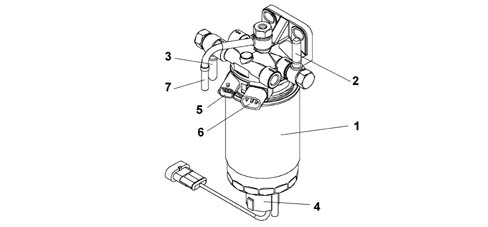
Fuel filter
The fuel filter is located in the engine bay on the driver's side and secured to the passenger compartment - engine bay bulkhead.The filter is cartridge type with a filter element. It is fitted with a fuel preheating device controlled by a thermal switch fitted to the filter. When diesel fuel temperature is lower than 6 °C, an electrical coil heats the fuel to a maximum of 15 °C before directing it to the pressure pump.A water presence sensor screwed to the base of the fuel filter cartridge also acts as a drain.
High-pressure pump
The radial jet type pressure pump has three radial pistons (total capacity 0.657 cc) and is operated by the timing belt.Each pumping unit consists of:
a piston (5) operated by a cam (2) in one piece with the pump shaft (6);
an intake valve (3);
a ball delivery valve (4);
The pump supply pressure should be at least 0.5 bar and, for this reason, the fuel system is equipped with an auxiliary pump submerged in the tank. The supply pressure is controlled by a pressure regulation valve fitted on the pressure pump.The pressure pump is lubricated and cooled by the actual diesel fuel by means of suitable ducts and can supply a maximum pressure of 1350 bar. The 3rd pumping exclusion device consists of a solenoid valve (1) which, by means of the push rod (2), keeps the intake alve (3) open during the 3rd pumping delivery stroke (5). It is activated by the control unit when the engine power does not increase at a speed of above 4200 rpm. The fuel dischraged in this way (~ ? of the capacity) is introduced into the high pressure pump recirculation circuit.
Fuel pressure regulator
The fuel pressure sensor is fitted on the pressure pump and is operated directly by the injection control unit; it regulates the fuel supply pressure to the injectors. The pressure regulator consists mainly of the following components:
Fuel tank cap with safety valve
The following figure contains a graph showing the operation of the valve inside the fuel tank cap.
The valve is located inside the fuel tank cap and carries out the following functions:
tank pressurisation;
ventilation;
seal in the case of roll-over.
Tank pressurisation is maintained by means of a valve in the tank cap. The tank pressure exceeds a specified value, overcomes spring resistance and allows the valve to lift so that vapour can emerge. The valve recloses when the pressure is restored to within limit values.Under specific vehicle operating conditions, a vacuum builds up in the tank. The valve allows air into the tank to restabilise pressure in the tank.The roll-over function prevents fuel emerging from the tank if the vehicle rolls over or tilts too far to one side.
Delivery manifold (rail)
The hydraulic accumulator is fitted to the cylinder head opposite to the intake side. With a volume of around 29 cm³, this damps fuel pressure fluctuations due to:
high pressure pump operation;
injector opening.
The fuel pressure sensor (2) and the pipes (3) connected to the injectors are fitted on the upper part of the hydraulic accumulator (1), whilst the low pressure fuel drain pipe (4) is fitted on the lower part.
Safety inertia switch
The vehicle is fitted with a safety inertia switch located on the engine bay on the dashboard wall near the battery to increase vehicle occupant safety during crashes.The sensor reduces the possibility of fire (due to emerging fuel) by deactivating the axiliary pump that feeds the injection circuit.
The inertia switch consists of a steel ball fitted in a housing (tapered seat) and maintained in position by the attractive force of a permanent magnet.In the case of violent vehicle impact, the ball is released from the magnetic detent and opens the normally closed (N.C.) electrical circuit to break the auxiliary fuel pump earth connection and hence the power supply to the injection system.Simply press the switch until it clicks home to restore the auxiliary pump earth connection.If a smell of fuel or fuel system leaks are noted after even an apparently slight impact, do not reset the inertia switch but find and repair the fault to prevent the risk of fire.
Intertia switch components
The following figure shows the inertia switch components