244000438 - INSTRUMENT PANEL
DESCRIPTION OF THE SYSTEM
Instrument panel control unit operation
The role of the control panel, produced by Magneti Marelli, is to display vehicle operating parameters and to notify the driver of any possible faults in the on-board electronic systems.The main functions performed by the instrument panel are listed below:- electronic speedometer and speedometer repeaters on the basic version with a speedomeer output. optional versions with four speedometer outputs with three active and one spare
- mileometer/trip counter
- electronic rev counter
- engine coolant temperature gauge with overheating warning light;
- fuel level gauge with reserve warning light and signal repetition unit;
- various warning lights (fault, activation etc.);
- panel lighting, graphics and pointers, with LEDs;
- LED mileometer lighting even during daylight;
- panel lighting and fixed graphics with lights on
- automatic transmission failure and speed engaged warning light for vehicles with automatic transmission
- clock function with hour and minute regulation
- engine oil level (only for optional versions)
- services.
| : When a ZF automatic transmission is fitted, the panel receives speed information via a serial line |
Composition
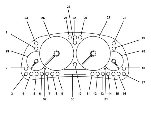
From a design point of view the panel consists of the following components:- two multifunction buttons for the milometer, servicing and time adjustment;
- speedometer reading with stepping motor;
- rev counter reading with stepping motor;
- LCD for milometer, clock, oil level, servicing, automatic transmission functions;
- fuel level gauge with stepping motor and LED reserve warning light;
- engine coolant temperature gauge with stepping motor and coolant overheating warning light LED;
- LED warning lights for signal functions;
- LED for SMD type (Surface Mounting Device) display and graphics
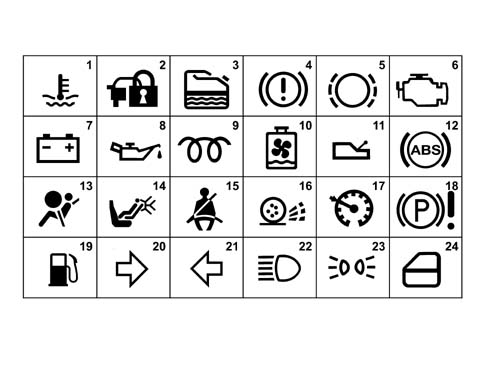
| NUMBER | WARNING LIGHT NAME | COLOUR | TYPE |
|---|---|---|---|
| 1 | Engine coolant overheating | RED | M |
| 2 | CODE system failure | AMBER | PL |
| 3 | Water in diesel filter warning light | AMBER | PH |
| 4 | Hanbrake/brake fluid level/EBD | RED | PL |
| 5 | Brake pad wear | RED | PL |
| 6 | Injection/EOBD failure | AMBER/RED | PL |
| 7 | Insufficient battery charge | RED | PL |
| 8 | Engine oil pressure | RED | PL |
| 9 | Heater plugs | AMBER | PL |
| 10 | Radiator coolant low level warning light | RED | PL |
| 11 | Automatic transmission failure | RED | M OPT |
| 12 | ABS | AMBER | PI OPT |
| 13 | Air Bag failure warning light | RED | PI |
| 14 | Passenger Air Bag disabling | AMBER | PL OPT |
| 15 | Seat belts not fastened | RED | PL OPT |
| 16 | Traction Control/ASR failure | AMBER | PL OPT |
| 17 | Cruise control on | GREEN | PL OPT |
| 18 | EPB failure (activated to earth +30 supply connected) | RED | PL OPT |
| 19 | Fuel reserve | AMBER | M |
| 20 | Right direction indicator | GREEN | PH |
| 21 | Left direction indicator | GREEN | PH |
| 22 | Main beam headlamps | BLUE | PL |
| 23 | Side lights | GREEN | PH |
| 24 | Doors open | RED | PL OPT |
| 25 | Spare 1 | PL | |
| 26 | Electronic speedometer | ||
| 27 | Electronic rev counter | ||
| 28 | Fuel level gauge | ||
| 29 | Engine coolant temperature gauge | ||
| 30 | Milometer LCD | ||
| 31 | Odometer and service button | ||
| 32 | Time adjustment button |
- PL = warning light activated at low level;
- PH = warning light activated at high level;
- PI = intelligent type warning light;
- M = warning light activated by micro-controller;
| the three warning lights activated by the micro-controller (CODE system failure warning light, automatic transmission failure warning lgiht and fuel reserve warning light) should be on with the ignition on for three seconds. If they are off when the ignition is on, then there is a failure. |
Instrument panel connectors
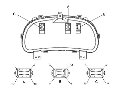
| PIN | SIGNAL |
|---|---|
| 1 | Speedometer 1 repetition for CCM |
| 2 | Water in diesel filter warning light |
| 3 | CODE warning light |
| 4 | Instrument earth |
| 5 | Speedometer impulse generator earth |
| 6 | Handbrake applied warning light |
| 7 | Injection/EOBD failure warning light |
| 8 | Reserved for Magneti Marelli |
| 9 | Engine coolant temperature sensor input |
| 10 | Direct supply (+30) |
| 11 | Main beam headlamps warning light |
| 12 | Supply controlled by ignition (+15) |
| 13 | Fuel level sensor earth |
| 14 | Fuel level sensor earth input |
| 15 | Speedometer input from impulse generator / CCA |
| 16 | Engine coolant overheating warning light CCM |
| 17 | Rev counter signal input |
| 18 | Radiator coolant level warning light |
| PIN | SIGNAL |
|---|---|
| 1 | Alternator recharging warning light |
| 2 | Brake pad wear warning light |
| 3 | Insufficient brake fluid level warning light |
| 4 | Heater plugs warning light |
| 5 | Right direction indicators warning light |
| 6 | Left direction indicators warning light |
| 7 | Insufficient engine oil pressure warning light |
| 8 | Air Bag failure warning light |
| 9 | Side lights warning light |
| 10 | Fuel reserve repeater |
| 11 | Engine oil level sensor/M.M.E.O.L. input |
| 12 | Engine oil level sensor earth |
| PIN | SIGNAL |
|---|---|
| 1 | Doors open warning light |
| 2 | Dimmer input (preparation) |
| 3 | Doors open warning light |
| 4 | Not connected |
| 5 | Not connected |
| 6 | ZF automatic transmission input |
| 7 | ABS failure warning light |
| 8 | EBD failure warning light |
| 9 | Cruise Control failure warning light |
| 10 | Spare warning light 1 |
| 11 | Main beam headlamps warning light |
| 12 | Speedometer repeater 4 |
| 13 | Speedometer repeater 3 (preparation) |
| 14 | Speedometer repeater 2 |
| 15 | Speedometer input from tachograph [b7] |
| 16 | Traction Control/ASR failure warning light |
| 17 | Passenger Air Bag disabled warning light |
| 18 | Not connected |
Lighting system
The instrument panel backlighting is activated when the signal from the lights is received, whilst the panel is not lit up when the headlamps are off. No other lighting control strategy is active on the panel while the mileometer display is automatically back-lit when the key is turned on.Odometer
The milometer is the digital electronic type with an LCD (liquid crystal display) with 1 line.The milometer display is illustrated in the diagram
- (a) when the total mileage is displayed pressing the button for between 0.1 seconds and 2 seconds produces a switching to the trip mileage when it is released;
- (b) when the trip mileage is displayed, pressing the button briefly (in other words between 0.1 and 2 seconds) produces a switch to the total mileage when the button is released; pressing the button for a while (between 2 and 5 secs) inolves zeroing the trip mileage displayed.
| The trip meter counter returns to display "0.0" when the figure "999.9" is exceeded, whilst when the total mileage counter exceeds 999999 (Km or Miles) it only displays the centre segments of all the digits (in other words 6 horizontal "bars"). |
Planned maintenance
The servicing function lets the user know when the vehicle is ready for service when the distance or time parameters approach the deadline set for the engine and application type.Distance and time parameters definitionThe parameters used for calculating the services are the distance travelled and time.The distance travelled is calculated using the vehicle speed input with an upper limit of 99999 Km and the time is indicated in days and taken from the clock function.There is a spanner symbol for the servicing function that appears each time the ignition is switched on if| ... DATA ERROR - CROPPED TEXT | Ошибка данных - Текст обрезан ... |
|---|